Lesson 08: SD Card File Read/Write
Applicable development board: CrowPanel Advanced 7 / 9 / 10.1-inch ESP32-P4 HMI AI Display Development Board
Model compatibility: The 7-inch, 9-inch, and 10.1-inch models are fully interchangeable in terms of hardware interfaces and software code, differing only in physical size. Please select a model based on the actual display size and use case; no code modifications are required for this lesson.
1. Course Introduction
Mount the SD card file system, create hello.txt, write hello world!, then read it back and print it.
2. Learning Objectives
After completing this lesson, you should be able to:
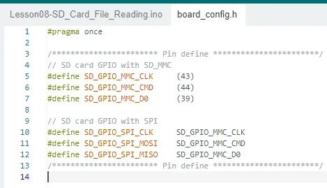
- Understand the centralized configuration of SD_MMC/SPI pins in
board_config.h. - Use file creation, string writing, and string reading functions.
- Understand the loop-based verification approach of the FreeRTOS
sd_task().
3. Preparations
- Hardware: One CrowPanel Advanced 7 / 9 / 10.1-inch ESP32-P4 HMI AI Display development board; one FAT32-formatted MicroSD card; one USB Type-C data cable that supports data transfer.
- The SD card must be formatted as a FAT file system; otherwise it may fail to be recognized correctly, and files on the card may fail to be read.
- Compatibility note: The hardware and software code for the 7 / 9 / 10.1-inch development boards are fully interchangeable, differing only in board size; please select the appropriate model based on display size and use case.
Code reference: https://github.com/Elecrow-RD/CrowPanel-Advanced-7inch-ESP32-P4-HMI-AI-Display-1024x600-IPS-Touch-Screen/tree/master/example
4. Software Operation Steps
Double-click to open the Lesson 8 code. (.ino file)
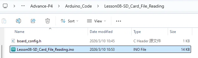
SD Card Pin Description
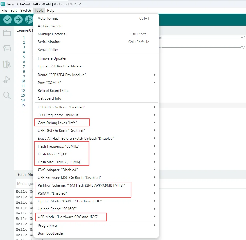
Configure the following options accordingly.
- Board:
ESP32P4 Dev Module - Core Debug Level:
Info - Flash Frequency / Mode / Size:
80MHz/QIO/16MB (128Mb) - Partition Scheme:
16M Flash (3MB APP/9.9MB FATFS) - PSRAM:
Enabled - USB Mode:
Hardware CDC and JTAG - Port: After connecting the USB data cable to the board's UART0, select the newly appeared COM port under "Tools → Port".
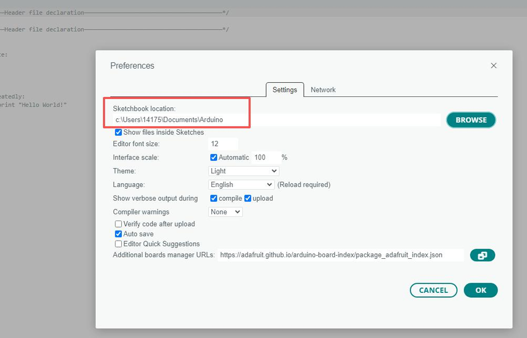
Following the library import steps explained in detail in Lesson 1, import the library files required for this project into the development environment, ensuring that the code can correctly locate the relevant dependencies during compilation, thereby guaranteeing proper program execution.
5. Hardware Operation Steps
Now that the code is ready, we need to flash the ESP32-P4 to see the results in action.
First, connect the Advance-P4 device to your computer host via a USB cable.
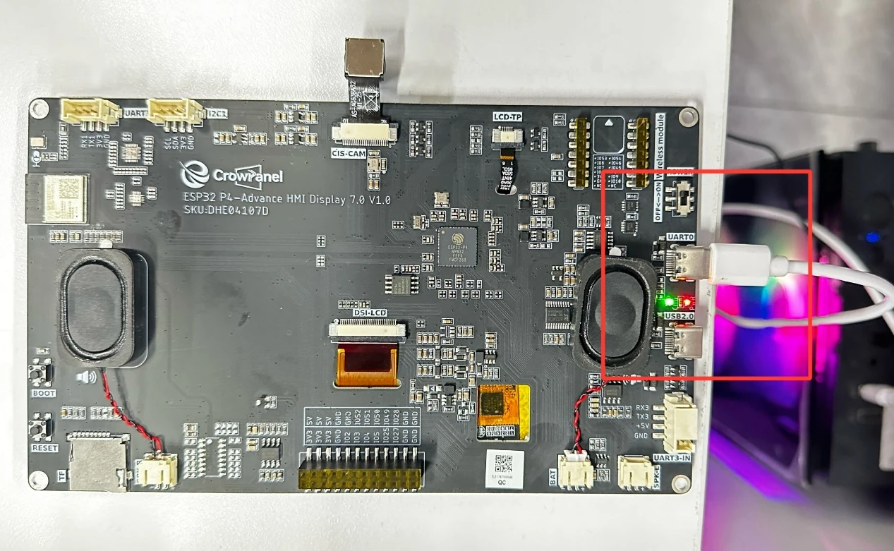
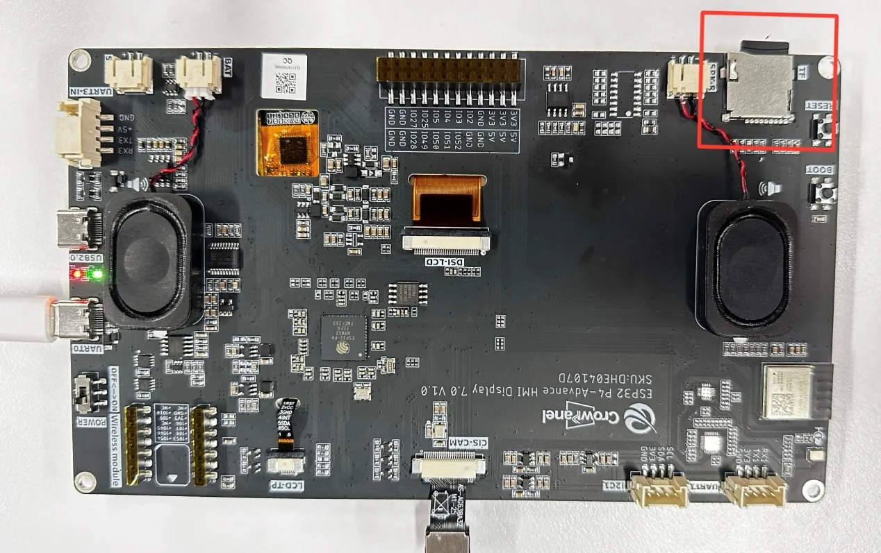
Power off, then insert the microSD card.
Before uploading the code, first select the upload configuration by following "4. Software Operation Steps."
Connect UART0 and compile/upload using the general configuration; keep the board powered.
6. Key Code Explanation
6.1 File Read/Write Interface
The write function opens and closes the file in write mode, and the read function obtains a line in read mode; it performs a null check on the file handle and returns ESP_FAIL on failure.
6.2 FreeRTOS Test Task
get_sd_card_info();
write_string_file(file_hello, data);
vTaskDelay(200 / portTICK_PERIOD_MS);
read_string_file(file_hello);
sd_task() executes the card-info, write, wait, read, and file-size checks in sequence. A short vTaskDelay() lets the write settle, and the task repeats the verification cycle periodically.
7. Experimental Results
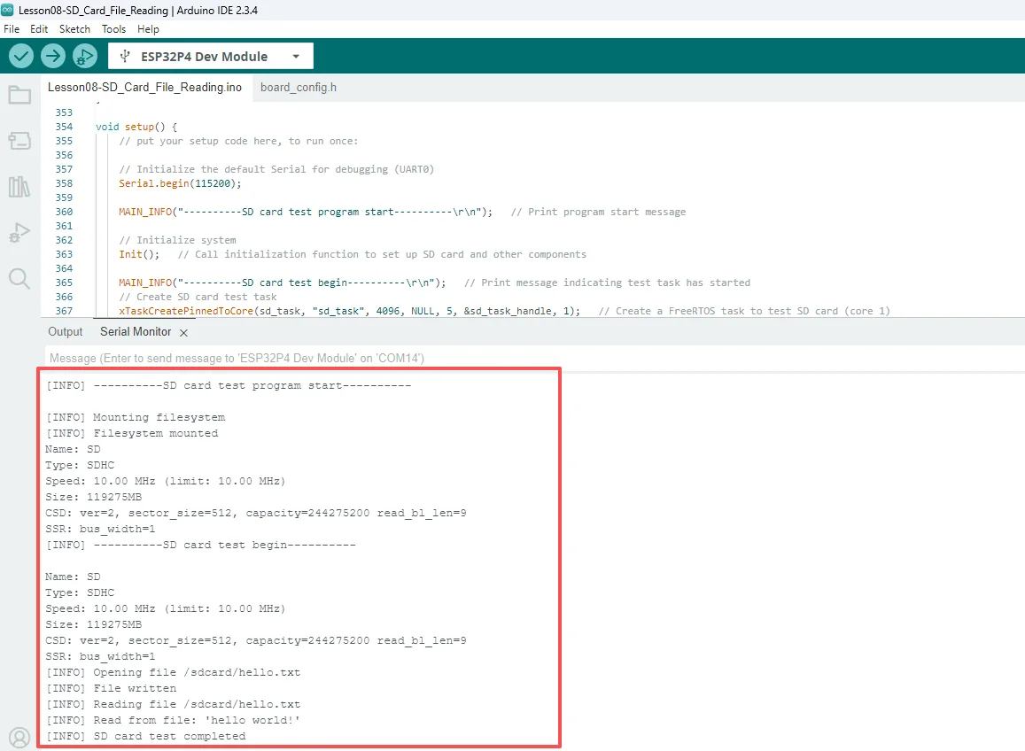
/hello.txtappears on the SD card with the contenthello world!; the serial monitor shows a successful write, the read-back content, and test completion.
(For how to open the serial monitor, please refer to Lesson 1, where we explain it in detail)
8. Frequently Asked Questions and Troubleshooting
- If mounting fails, power off, re-insert the SD card, and check the format.
- If the write succeeds but the read is empty, check the file path, the timing of closing the file, and the card's write-protection status.