Lesson 09: LVGL Touch Control of LED
Applicable development board: CrowPanel Advanced 7 / 9 / 10.1-inch ESP32-P4 HMI AI Display Development Board
Model commonality: The 7-inch, 9-inch, and 10.1-inch models are fully interchangeable in terms of hardware interfaces and software code; only their physical dimensions differ. Please select a model based on the actual display size and use case. No code modifications are required for this lesson.
1. Course Introduction
Create LED ON and LED OFF buttons on the LVGL screen; when a button is tapped, GPIO48 is used to control the UART1 LED.
2. Learning Objectives
After completing this lesson, you should be able to:
- Understand the connection between LVGL event callbacks and GPIO output.
- Correctly acquire and release the LVGL lock before and after creating the UI.
- Use touch buttons to complete LED on/off control.
3. What You Need to Prepare
- Prepare the CrowPanel Advanced 7 / 9 / 10.1-inch ESP32-P4 HMI AI Display Development Board and a data-capable USB-C cable as required for this lesson.
- LVGL 9.1; the project includes display/touch port files and board-level configuration.
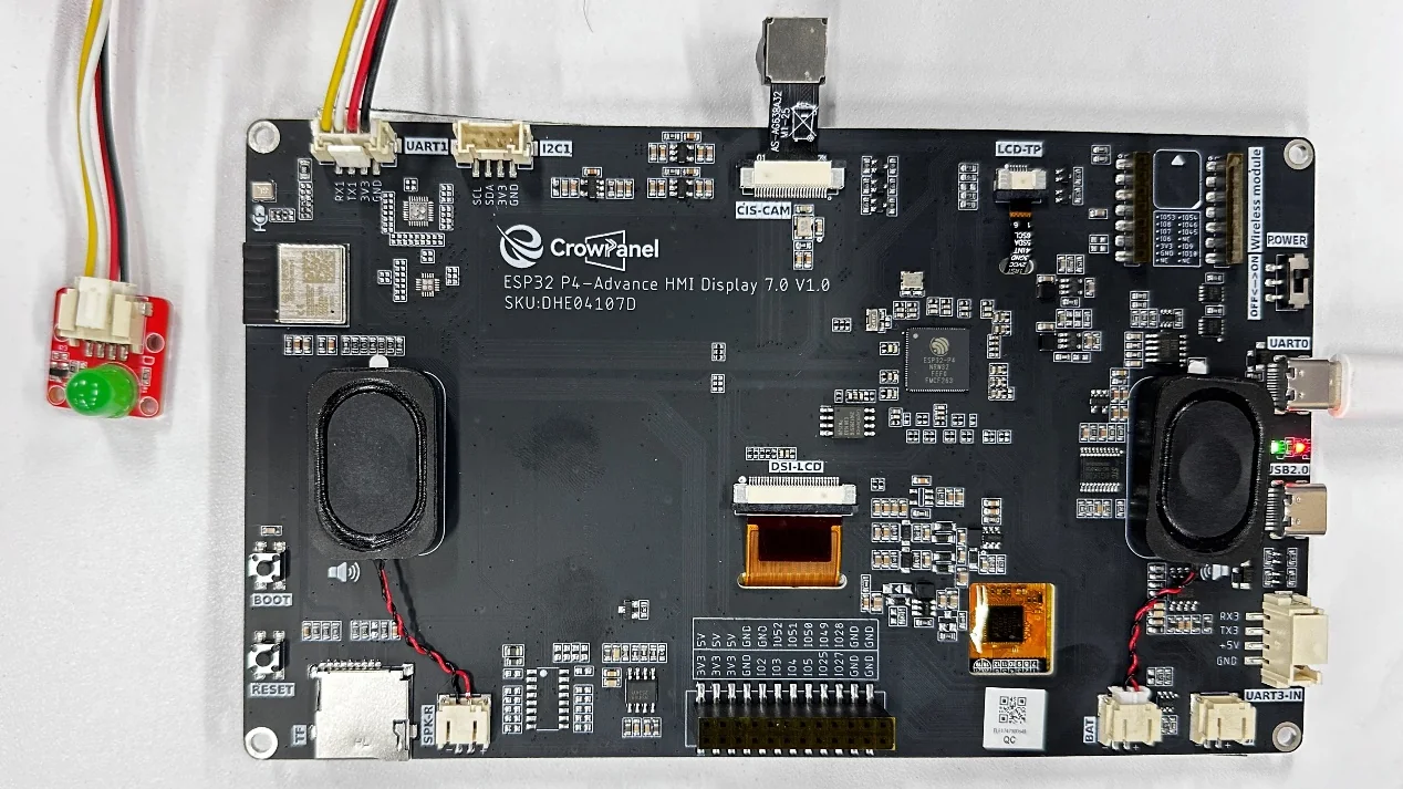
- The LED remains connected to GPIO48 of UART1.
Code reference: https://github.com/Elecrow-RD/CrowPanel-Advanced-7inch-ESP32-P4-HMI-AI-Display-1024x600-IPS-Touch-Screen/tree/master/example
4. Software Operation Steps
Double-click to open the Lesson 9 code (.ino file).
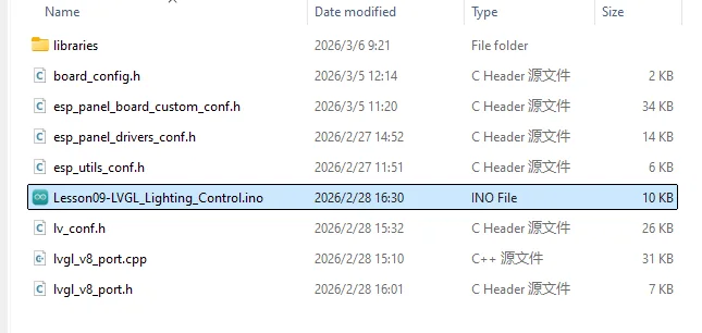
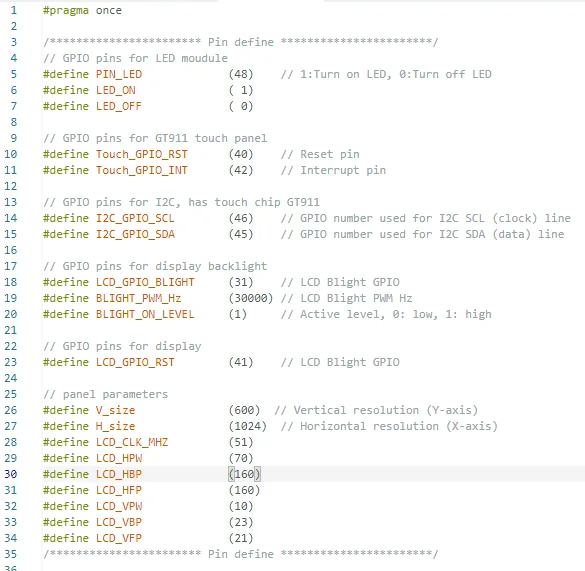
Screen pinout and related control pin descriptions
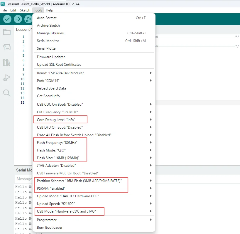
Configure the options below.
- Board:
ESP32P4 Dev Module - Core Debug Level:
Info - Flash Frequency / Mode / Size:
80MHz/QIO/16MB (128Mb) - Partition Scheme:
16M Flash (3MB APP/9.9MB FATFS) - PSRAM:
Enabled - USB Mode:
Hardware CDC and JTAG - Port: After connecting the USB data cable to the board's UART0, select the newly appeared COM port under "Tools → Port".
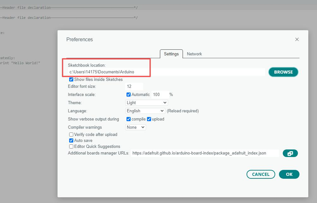
Follow the library import steps detailed in Lesson 1 to import the library files required by this project into the development environment, ensuring that the code can correctly locate the relevant dependencies during compilation, thereby guaranteeing normal program operation.
5. Hardware Operation Steps
Now that the code is ready, we need to flash the ESP32-P4 to see the results in action.
First, connect the Advance-P4 device to your computer host via a USB cable.
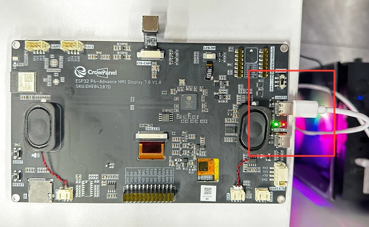
The LED connects to GPIO48 of UART1, and the screen displays the buttons and receives touch events; check the wiring with power off.
Before uploading the code, first select the upload configuration by following "4. Software Operation Steps."
Connect UART0 and compile and upload using the general configuration; keep the board powered.
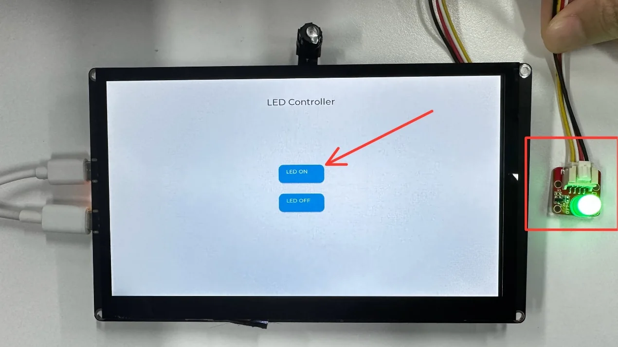
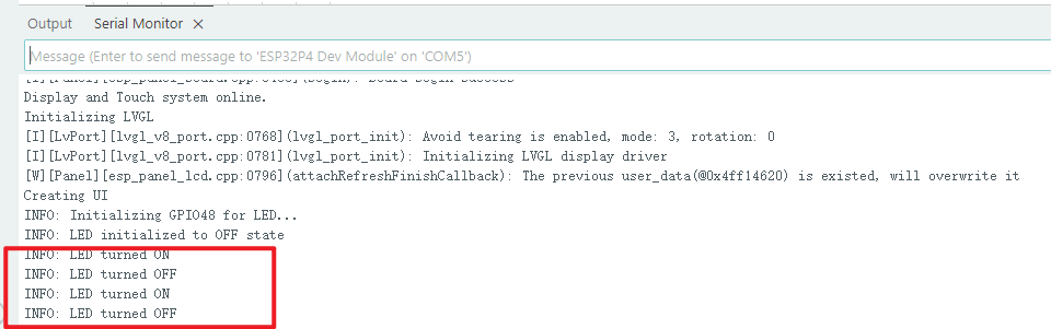
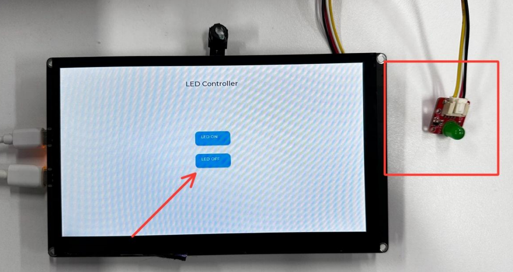
Connect UART0 to upload; after startup, tap the two buttons on the screen—each tap should toggle the LED and output a log.
If you don't know how to open the serial monitor, please refer to Lesson 1.
6. Key Code Explanation
6.1 Button Event Callback
static void btn_on_click_event(lv_event_t *e) {
  (void)e;
  digitalWrite(PIN_LED, LED_ON);
  MAIN_INFO("LED turned ON");
}

static void btn_off_click_event(lv_event_t *e) {
  (void)e;
  digitalWrite(PIN_LED, LED_OFF);
  MAIN_INFO("LED turned OFF");
}
Each callback writes the active level defined by LED_ON/LED_OFF to PIN_LED and logs the new state; (void)e marks the event parameter as unused.
6.2 create_led_control_ui()
if (lvgl_port_lock(-1) != true) return;
lv_obj_t *btn_on = lv_button_create(scr);
lv_obj_add_event_cb(btn_on, btn_on_click_event,
                    LV_EVENT_CLICKED, NULL);
lvgl_port_unlock();
The function locks LVGL, sets the active-screen background, creates the title and two lv_button_create() buttons with labels, binds LV_EVENT_CLICKED, and unlocks LVGL. The lock scope covers only UI operations.
7. Experimental Observations
When LED ON is tapped, GPIO48 goes to the LED_ON level, turning the LED on.
When LED OFF is tapped, GPIO48 goes to the LED_OFF level and the LED turns off.
8. Common Issues and Troubleshooting
- If buttons are unresponsive, check the LVGL initialization and touch driver.
- If the LED logic is inverted, refer to the active-level macros in
config.h/board_config.h.