Lesson01_IDF_HelloWorld: Printing "Hello World" over Serial on ESP32-P4
1. Course Introduction
In this lesson, we use the ESP-IDF framework to run our first program on the ESP32-P4. A FreeRTOS main task prints an incrementing counter to the serial port once per second. After the program is flashed and the board is powered on and reset, the serial monitor first outputs the ESP-IDF startup information, then prints a line such as Hello world: 0, Hello world: 1… once per second, with the counter continuing to increment. Learners only need to connect a USB data cable, complete the ESP-IDF environment setup, compile, and flash the program to see continuous serial output.
This lesson is the first in the entire ESP32-P4 curriculum. It involves no peripheral drivers and focuses on verifying whether the development environment and the communication link with the development board are working properly. Through this experiment, learners will complete the full introductory chain of opening an ESP-IDF project, setting the target chip, compiling, flashing, and serial monitoring, laying the environmental foundation for subsequent lessons such as lighting up an LED and driving a display.
2. Learning Objectives
- Be able to open the Lesson01 project in the ESP-IDF environment and set the target chip to
esp32p4. - Be able to explain when
app_mainis invoked as the default task entry point in ESP-IDF, and the role ofvTaskDelaywithin the loop. - Be able to complete project compilation and flashing, and open the serial monitor to observe the
Hello worldcounter output. - Be able to determine whether the development environment and communication link are working properly based on whether the serial port continuously prints incrementing counts.
3. What You Need to Prepare
- Hardware: One CrowPanel Advanced 7 / 9 / 10.1-inch ESP32-P4 HMI AI Display development board, and one USB Type-C data cable that supports data transfer.
- Compatibility note: The 7 / 9 / 10.1-inch development boards share the same hardware and software code; only the board dimensions differ. Please select the appropriate model based on the display size and use case.
- Software: VS Code, ESP-IDF Extension (ESP-IDF and its toolchain must be installed; v5.5.4 or later is recommended). This lesson uses v5.5.4.
- Project dependencies: Keep the
CMakeLists.txtandmain/hello_world_main.cfiles under theLesson01-Print_Hello_Worlddirectory. This lesson requires no additional components to be installed. - Configuration: target chip
esp32p4.
Code download link:
4. Software Operation Steps
Open the ESP-IDF Extension panel in VS Code, click Open ESP-IDF Project, and select the Lesson01-Print_Hello_World folder. If you need to create a new project from a template, fill in the project name, target chip, and serial port in the ESP-IDF panel, then select a template.
You can also right-click the course directory in File Explorer and choose to open it with VS Code.
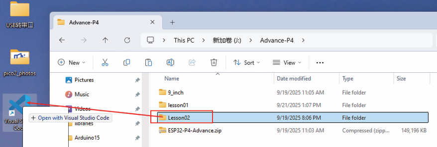
After opening, the Explorer on the left should display the project files such as main and CMakeLists.txt.

Open main/hello_world_main.c and confirm that the app_main, printf, and vTaskDelay code is complete.
First, select the ESP-IDF v5.5.4 runtime environment.
For installation steps, refer to: Get Started with ESP IDF - Elecrow Wiki
Then set the flashing method to UART.
Next, select the serial port that actually corresponds to the development board.
In the ESP-IDF Extension panel, click Set Espressif Device Target and select esp32p4 from the pop-up target list. After the setting is complete, the target chip in the status bar should display ESP32-P4.

Click SDK Configuration Editor in the VS Code status bar at the bottom or in the ESP-IDF extension panel, and wait for the configuration page to fully load before modifying parameters. If the page is still loading, wait for it to finish loading first.

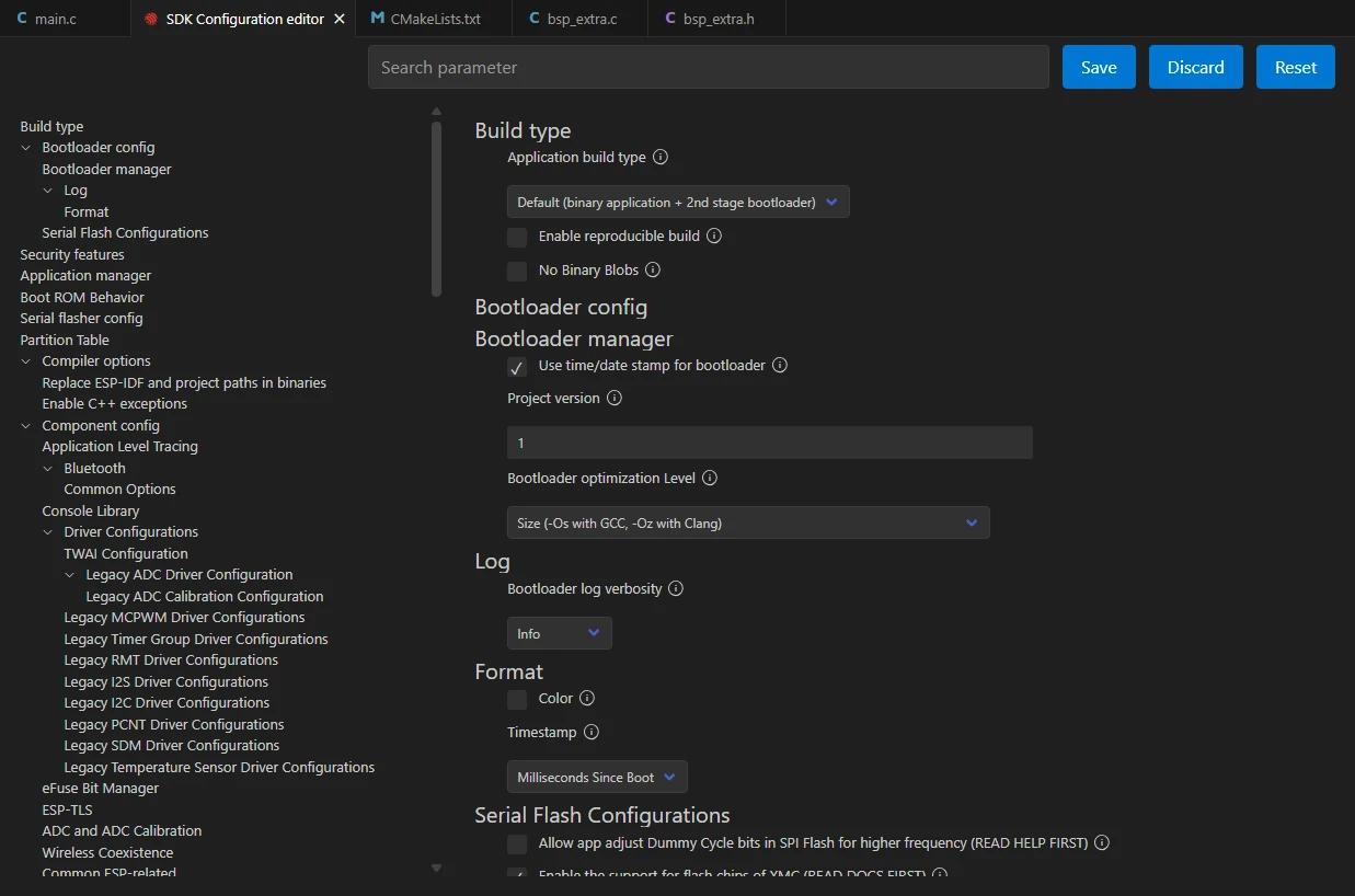
Enter flash in the search box and ensure Flash SPI mode: QIO; Flash Sampling Mode: STR Mode; Flash SPI speed: 80 MHz; Flash size: 16 MB. These parameters should match the onboard Flash of the Advance-P4 board.

This lesson does not require enabling any additional components; keep the remaining SDK options at their project defaults. After verifying the Flash parameters above are correct, click Save in the upper right corner, and compile only after the save is successful.
Then click Full Clean to clear the previous build cache; this does not affect compiling the new code.

Click the Build button and wait for compilation to complete. On success, the output window should end with Project build complete and show no error messages.
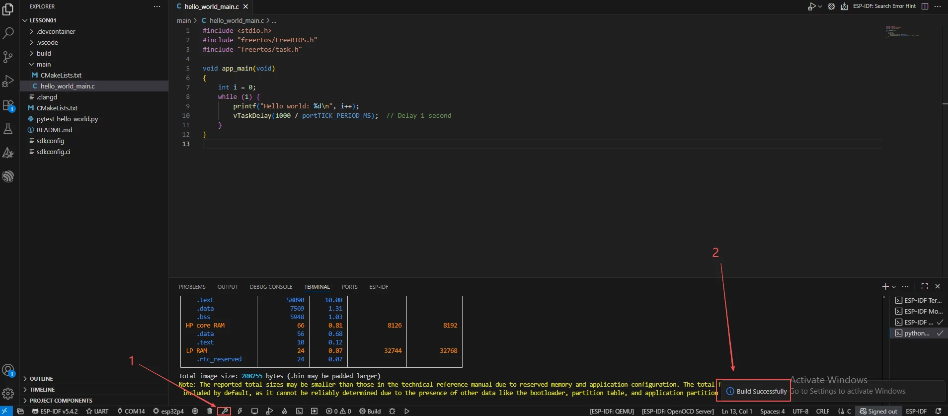
After confirming that the development board is connected to the computer via the USB data cable, click Select Port to Use to choose the corresponding serial port (e.g., COM14).
Then click the Flash button. During flashing, the output window shows the progress; upon completion, it displays Hash of data verified and Hard resetting....

After flashing is complete, click the Monitor button to open the serial monitor; the baud rate defaults to 115200. Once the monitor opens, it should first display the ESP-IDF startup information, then continuously print the Hello world counter. Press Ctrl + ] to exit the monitor.
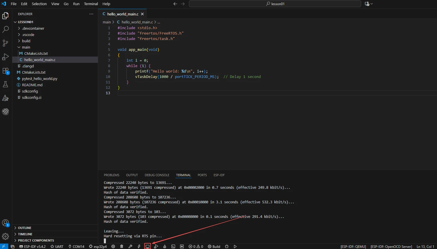
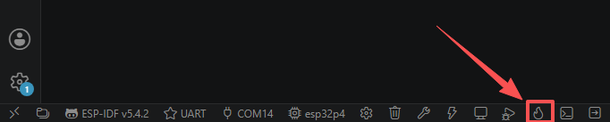
Finally, we introduce a one-click action button that can continuously complete compilation, flashing, and opening the serial monitor. Use it only after the project configuration and serial port are confirmed to be correct.
5. Hardware Operation Steps
Connect the ESP32-P4 development board's UART0 interface to the computer using a USB Type-C data cable that supports data transfer. After connecting, the board's power indicator should light up. 
After flashing is complete and the board is reset, observe whether the development board starts up normally. If the serial monitor is already open, you should see the ESP-IDF startup information, including the chip model ESP32-P4 and the reset reason.
Observe whether the serial monitor prints a line Hello world: N once per second, where N starts from 0 and increments continuously, with no restart or freeze occurring. The serial output should be consistent with the loop and delay logic in the main program.
6. Key Code Explanation
In this lesson, we only include the standard input/output and FreeRTOS header files. freertos/task.h provides task management interfaces such as vTaskDelay and is a basic header file used in all subsequent lessons. Removing freertos/task.h will cause vTaskDelay to be unrecognized, resulting in a compilation error.
app_main is the default user entry point in ESP-IDF. After the system starts, ESP-IDF automatically creates a FreeRTOS task named main and calls app_main; no manual invocation is needed. If the function name is changed to something else, the program will still compile, but the logic inside it will not execute and the serial port will not print anything. This behavior can be used to determine whether the issue is "the entry point not taking effect" or "a logic error".
i is the counter variable, incremented after each loop's print, corresponding to the continuously incrementing numbers in the serial output. while (1) ensures the program runs in a loop. vTaskDelay(1000 / portTICK_PERIOD_MS) converts 1000 milliseconds into tick counts, delaying the current task by 1 second. This line is critical: if it is removed or commented out, the loop will print continuously without delay, and the serial output may flood the screen due to excessive speed, even affecting the scheduling of other tasks; after restoring this line, the print frequency returns to once per second. portTICK_PERIOD_MS represents the number of milliseconds per tick.
7. Experimental Observations
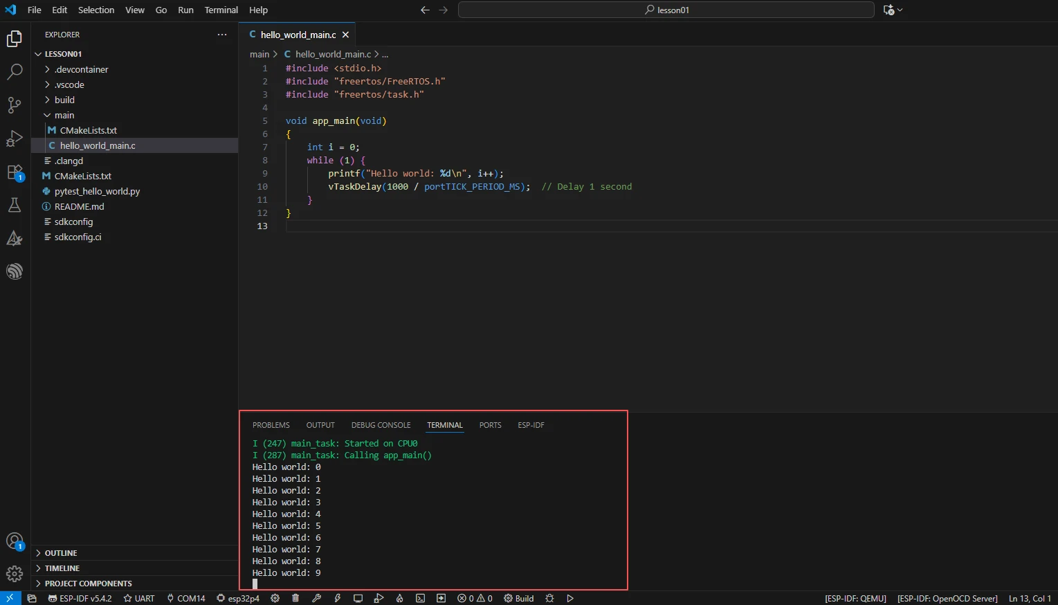
After the program is flashed and reset, the serial monitor first outputs the ESP-IDF startup information, including the chip model ESP32-P4, CPU frequency, reset reason, and so on. It then enters the user program and prints one incrementing line per second starting from Hello world: 0:
Printing should continue, with the counter incrementing continuously, and the development board should not restart, freeze, or produce no output for an extended period. If the serial port shows no output at all, first check whether the correct serial port is selected, whether the baud rate is 115200, and whether the target chip is esp32p4; if garbled characters appear, it is mostly caused by a baud rate mismatch.