Lesson03_UART3-IN: ESP32-P4 UART3-IN External Power Supply and Serial Interface Description
1. Course Introduction
This lesson introduces the UART3-IN interface on the CrowPanel Advanced 7-inch ESP32-P4 development board. This interface can be used to supply external power to the development board, and can also serve as a standard serial communication interface. Although it is located near the UART0 interface used for firmware flashing, its function is different.
This lesson is purely theoretical and covers hardware connection instructions only. It does not add new code, modify SDK configuration, or perform compilation or flashing. The experiment reuses the LED program already flashed in Lesson02: after UART3-IN supplies power correctly, the onboard LED will continue to blink according to the original program, serving as verification that the power supply chain is functioning properly.
2. Learning Objectives
- Be able to locate the
UART3-IN,UART0,VCC,GND,RX3, andTX3labels on the development board. - Be able to explain the differences between
UART0andUART3-INin terms of flashing, power supply, and serial communication. - Be able to use an external adjustable power supply to input
5Vpower into the development board through UART3-IN. - Be able to correctly connect the positive and negative terminals of the external power supply, and use the flashed LED blinking behavior to confirm that power supply has succeeded.
- Be able to explain why externally connected devices must be independently powered and share a common ground with the development board when UART3-IN is used as a standard serial port.
3. Preparations
- Hardware: one CrowPanel Advanced 7 / 9 / 10.1-inch ESP32-P4 HMI AI Display development board.
- Compatibility note: The 7 / 9 / 10.1-inch development boards share identical hardware and software code, differing only in board size; please select the appropriate model based on display size and usage scenario.
- Power supply: one adjustable DC power supply, with output voltage set to
5Vand current limit set to2A. - Cables: two Dupont wires, one connecting to
VCCand one toGND. - Verification program: it is recommended that the development board has the Lesson02 LED blinking program flashed, for observing the operating state after external power supply.
- Software and code: this lesson is purely theoretical; there is no need to download code, open VS Code, or compile or flash.
Code download link: this lesson is purely theoretical and requires no code download.
4. UART0 and UART3-IN Interface Description
UART3-IN is located on the lower-right side of the development board, with RX3, TX3, 5V, and GND marked beside the interface. Before connecting an external power supply or serial device, first confirm the function of each wire against the silkscreen to avoid reversing the positive and negative terminals of the power supply.
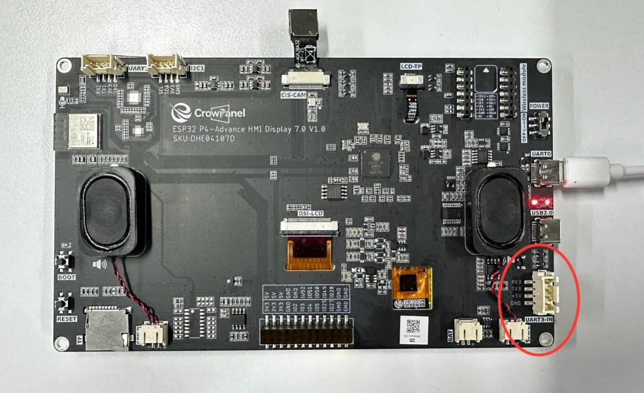
UART0 is the interface used in the course to upload programs. It connects to the onboard serial flashing chip, so it can be used for ESP-IDF firmware flashing. After UART0 is connected, the development board also receives power, and the power indicator light will turn on.
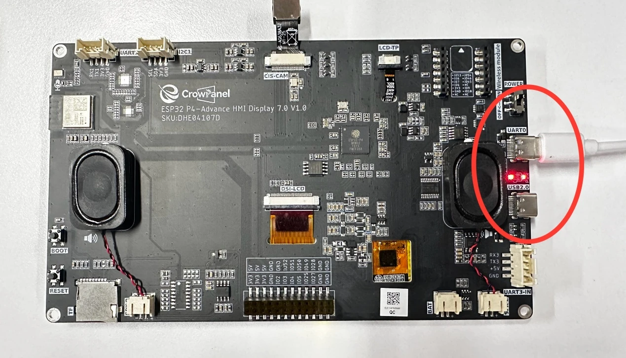
The power supply function of UART3-IN is similar to that of UART0; both can feed power into the development board. However, UART3-IN is not connected to a serial flashing chip, so it cannot be used to upload programs. UART0 should still be used when flashing is required.
UART3-IN can also be used as a standard serial interface, in which case RX3 and TX3 are used for data communication. The two communicating parties must be correctly cross-connected and share GND. UART3-IN does not provide operating power to externally connected devices, which must have their own independent power supply.
5. Using UART3-IN for External Power Supply
First turn off the adjustable power supply output and prepare two Dupont wires. Connect one wire to the VCC of UART3-IN and the other to GND. Do not plug or unplug power wires while the power supply is on.
Set the adjustable power supply output to 5V and the current limit to 2A. Confirm that the positive output corresponds to VCC and the negative output corresponds to GND.
Connect the positive terminal of the power supply to the VCC of UART3-IN, and the negative terminal to the GND of UART3-IN. After wiring, check again the polarity, whether the Dupont wires are securely fastened, and whether the wires were mistakenly connected to the RX3 or TX3 pins.
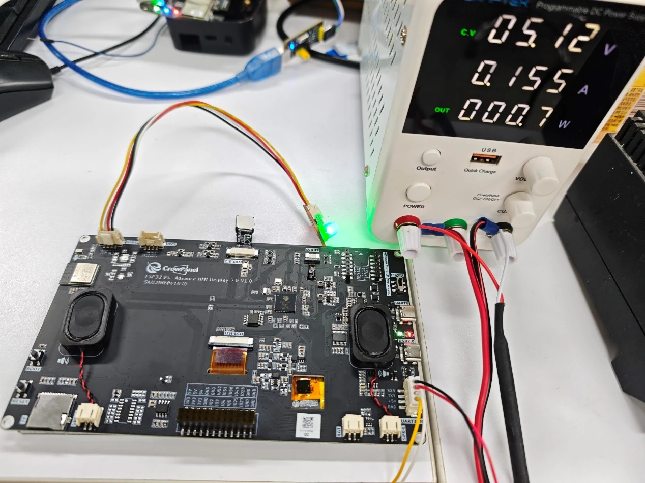
Only turn on the power supply output after confirming the wiring is correct. The development board's power indicator lighting up indicates that external power has been received. If the power supply enters current limiting, the indicator fails to light up, or the board overheats abnormally, immediately turn off the power supply and inspect the wiring.
If the development board still holds the Lesson02 LED blinking program, after external power supply you can observe the LED continuing to blink at a rhythm of approximately 1 second on and 1 second off. This indicates that the UART3-IN external power supply chain is normal and the development board has successfully run the original program.
6. Key Precautions
UART3-IN can only be used for external power supply input and standard serial communication; it cannot replace UART0 for program flashing.
The external supply voltage must be 5V. Before wiring, be sure to confirm VCC and GND; do not reverse the positive and negative terminals, and do not connect the power wires to RX3 and TX3.
When UART3-IN is used for serial communication, externally connected devices require their own power supply; connecting only RX3, TX3, and the common ground wire cannot power externally connected devices.
When a power supply abnormality occurs, first turn off the power supply, then troubleshoot the voltage setting, polarity, contact condition, and possible short circuit. Do not arbitrarily adjust the Dupont wires while power is on.
7. Lesson Summary
UART0 handles program flashing and can power the development board; UART3-IN can feed external power into the development board and also serve as a standard serial interface, but it does not have flashing capability.
Through the 5V external power supply and the LED blinking phenomenon carried over from Lesson02, this lesson verified the power supply function of UART3-IN, laying the hardware foundation for subsequently using external power supplies or externally connected serial devices.