Lesson04_UART_AT_WiFi: ESP32-P4 Serial Communication and AT Command Networking
1. Course Introduction
This lesson uses the ESP-IDF UART driver to perform serial communication between the ESP32-P4's UART1 (TX=GPIO47, RX=GPIO48) and an external WiFi module. After the program is flashed, the development board uses AT commands to control the WiFi module, switching it to AP+STA mode, connecting to a designated router, querying the IP address, and starting a TCP server. The serial monitor prints each AT command and the module's responses in real time.
This lesson builds on the GPIO basics from Lesson02 and introduces UART serial communication and AT command interaction for the first time. Learners should prepare a WiFi module that supports AT command control (e.g., ESP8266). Through this experiment, learners will complete the full-chain verification of UART initialization, data transmission and reception, AT command sending, and response parsing.
2. Learning Objectives
- Be able to open the Lesson04 project in ESP-IDF and set the target chip to
esp32p4. - Be able to explain the call order and roles of
uart_driver_install,uart_set_pin, anduart_param_config. - Be able to explain why AT commands end with
\r\n, and how to determine whether a command executed successfully. - Be able to complete compilation and flashing, and observe the interaction of AT commands and responses in the serial monitor.
- Be able to determine whether module communication is normal based on whether the serial output prints
OKandWiFi Connected.
3. Preparations
- Hardware: One CrowPanel Advanced 7 / 9 / 10.1-inch ESP32-P4 HMI AI Display development board; one WiFi module supporting AT command control (e.g., ESP8266); several jumper wires; one USB Type-C data cable.
- Compatibility note: The hardware and software code for the 7 / 9 / 10.1-inch development boards are fully interchangeable; only the board dimensions differ. Please select the appropriate model based on display size and usage scenario.
- Wiring: ESP32-P4's GPIO47 (TX) connects to the WiFi module's RX; ESP32-P4's GPIO48 (RX) connects to the WiFi module's TX; common ground.
- Software: VS Code, ESP-IDF Extension (ESP-IDF v5.5.4 and above).
- Project dependencies: Keep the
main/main.candperipheral/bsp_uartcomponents. - Network: An available 2.4 GHz WiFi router; the SSID and password must be written into the
WIFI_SSIDandWIFI_PASSmacros inmain.c.
Code download link:
4. Software Operation Steps
Open the ESP-IDF Extension panel in VS Code, click Open ESP-IDF Project, and select the Lesson04-Serial_port_usage folder.

First select the code runtime environment ESP-IDF v5.5.4, set the flashing method to UART, and then select the serial port corresponding to the actual development board. Then click Set Espressif Device Target in the ESP-IDF Extension panel and select esp32p4. After setup, the status bar should display ESP-IDF v5.5.4, UART, the required COM port, and ESP32-P4.

To modify WiFi information, open main/main.c and change WIFI_SSID and WIFI_PASS to your own router's SSID and password, then save the file.

Click SDK Configuration Editor in the VS Code bottom status bar or the ESP-IDF extension panel, and wait for the configuration page to fully load before modifying parameters. If the page is still loading, do not execute Build immediately.


Enter flash in the search box and ensure Flash SPI mode: QIO; Flash Sampling Mode: STR Mode; Flash SPI speed: 80 MHz; Flash size: 16 MB. These parameters should match the on-board Flash of the Advance-P4.

After verifying the configuration is correct, click Save in the upper-right corner; confirm the changes are saved, then execute Build to compile.
Click Full Clean to clear the cache left by the previous compilation. Performing this operation after the first compilation, switching project configurations, or modifying SDK parameters can prevent old configurations from affecting new compilation results.

Click Build to compile the project. On success, the end of the output window shows Project build complete.

After confirming the development board and WiFi module are correctly wired, click Select Port to Use to select the serial port, then click Flash to flash the firmware.

After flashing completes, click Monitor to open the serial monitor at a baud rate of 115200. You should see logs of AT commands being sent and the module's responses. Press Ctrl + ] to exit the monitor.

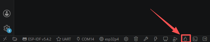
Finally, you can use the one-click operation button in the ESP-IDF status bar to sequentially execute build, flash, and open the serial monitor. Use this only after the project configuration, serial port, and code have all been confirmed correct; if you need to locate problems, follow the steps above and execute them item by item.
5. Hardware Operation Steps
With the power off, use jumper wires to connect ESP32-P4's GPIO47 (TX) to the WiFi module's RX, connect GPIO48 (RX) to the WiFi module's TX, and connect the GND of both. Note that TX/RX must be cross-connected.

Use a USB data cable to connect the ESP32-P4 development board to the computer; the board's power indicator lights up.

After flashing completes and the board resets, observe whether the WiFi module indicator lights work normally (typically a power light and a connection status light).

In the serial monitor, observe whether AT+CWMODE, AT+RST, AT+CWJAP, and other commands are printed in sequence along with their returned OK, and finally WiFi Connected and the IP address are printed.

6. Key Code Explanation
const uart_config_t uart_config = {
    .baud_rate = 115200,
    .data_bits = UART_DATA_8_BITS,
    .parity = UART_PARITY_DISABLE,
    .stop_bits = UART_STOP_BITS_1,
    .flow_ctrl = UART_HW_FLOWCTRL_DISABLE,
    .source_clk = UART_SCLK_DEFAULT,
};
err = uart_driver_install(UART_NUM_2, 1024 * 2, 0, 0, NULL, 0);
uart_set_pin(UART_NUM_2, UART1_EXTRA_GPIO_TXD, UART1_EXTRA_GPIO_RXD, ...);
uart_param_config(UART_NUM_2, &uart_config);
This is the initialization sequence for UART2. uart_config defines the 115200-8N1 parameters; uart_driver_install installs the driver and allocates a 2 KB receive buffer; uart_set_pin maps UART2's TX/RX to GPIO47/GPIO48; uart_param_config applies the communication parameters. The call order must be: install the driver first, then set the pins, and finally configure the parameters. If TX/RX are connected in reverse (for example, TX to TX), the module will not receive any commands, and the serial log will keep timing out with no response.
AT commands must end with a carriage return and line feed (\r\n) for the module to parse and execute them. If you only send SendData(cmd) without appending \r\n, the module will keep waiting for the newline character and will not return OK, appearing as an unresponsive command.
while ((xTaskGetTickCount() - start) < timeout && total < (int)len - 1) {
    read_bytes = uart_read_bytes(UART_NUM_2, (uint8_t *)(buffer + total),
                                 len - total - 1, 20 / portTICK_PERIOD_MS);
    if (read_bytes > 0) {
        total += read_bytes;
    }
}
buffer[total] = '\0';
uart_read_response accumulates short UART2 reads until the overall timeout expires or the response buffer is full, then null-terminates the result for string processing. This handles AT responses split across multiple UART frames; reading only once could miss the later OK token.
for (int i = 0; i < 5; i++) {
    if (connect_wifi()) { connected = true; break; }
    vTaskDelay(pdMS_TO_TICKS(2000));
}
WiFi connection may fail because the module is not yet ready right after reset; here it retries up to 5 times, with a 2-second interval each time. If you remove the retry logic, an occasional first-time failure will cause the task to exit directly, preventing network establishment.
7. Experimental Phenomena
After the program is flashed and reset, the serial monitor should output, in sequence, the AT command transmission content, the module responses, and the networking status.
If the WiFi module is wired correctly and the router is reachable, the serial port should print WiFi Connected and the IP address obtained by the module within a few seconds. If AT Response remains empty or does not contain OK, first check whether TX/RX are reversed and whether the module baud rate is 115200; if WiFi connection fails, check whether the SSID and password are correct, and whether the module supports 2.4 GHz networks.