Lesson08_SDMMC_File_IO: ESP32-P4 SD Card File Read/Write
1. Course Introduction
This lesson uses ESP-IDF to mount an SD card as a FAT file system via the SDMMC host driver, create a hello.txt file on the card, write the string hello world!, then read back the content and print it. After the program is flashed, the development board powers on and resets; the SD card (SDMMC, CLK=GPIO43, CMD=GPIO44, D0=GPIO39, 1-bit mode) is mounted to /sdcard, and the serial monitor prints the card information, as well as the write and read results.
This lesson is the foundation of the storage course, introducing SDMMC host and FAT-on-VFS file operations for the first time. Through this experiment, learners will complete the full-chain verification of SD card initialization, file system mounting, file creation, and write/read operations.
2. Learning Objectives
- Be able to open the Lesson08 project in ESP-IDF and set the target chip to
esp32p4. - Be able to explain the role of
esp_vfs_fat_sdmmc_mount, and why SDMMC host and slot configuration are required. - Be able to explain the relationship between the VFS mount point
/sdcardand the standard C file APIs (fopen/fprintf/fgets). - Be able to complete compilation and flashing, and observe whether the serial port prints the written and read content.
- Be able to determine whether the SD card wiring and file system are functioning normally based on whether mounting succeeds and whether read and write are consistent.
3. Preparations
- Hardware: One CrowPanel Advanced 7 / 9 / 10.1-inch ESP32-P4 HMI AI Display development board; one FAT32-formatted MicroSD card; one USB Type-C data cable that supports data transfer.
- The SD card must be formatted as a FAT file system; otherwise it may fail to be recognized correctly, and files on the card may fail to be read.
- Compatibility note: The hardware and software code for the 7 / 9 / 10.1-inch development boards are fully interchangeable, differing only in board size; please select the appropriate model based on display size and use case.
- Software: VS Code, ESP-IDF Extension (ESP-IDF v5.5.4 or above).
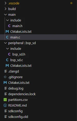
- Project dependencies: retain the
main/main.cfile, theperipheral/bsp_sdcomponent, and thesdmmc_cmdandesp_vfs_fatmanaged components. - Configuration: target chip
esp32p4.
Code download link:
4. Software Operation Steps
In VS Code, open the ESP-IDF Extension panel, click Open ESP-IDF Project, and select the Lesson08-SD_Card_File_Reading folder.
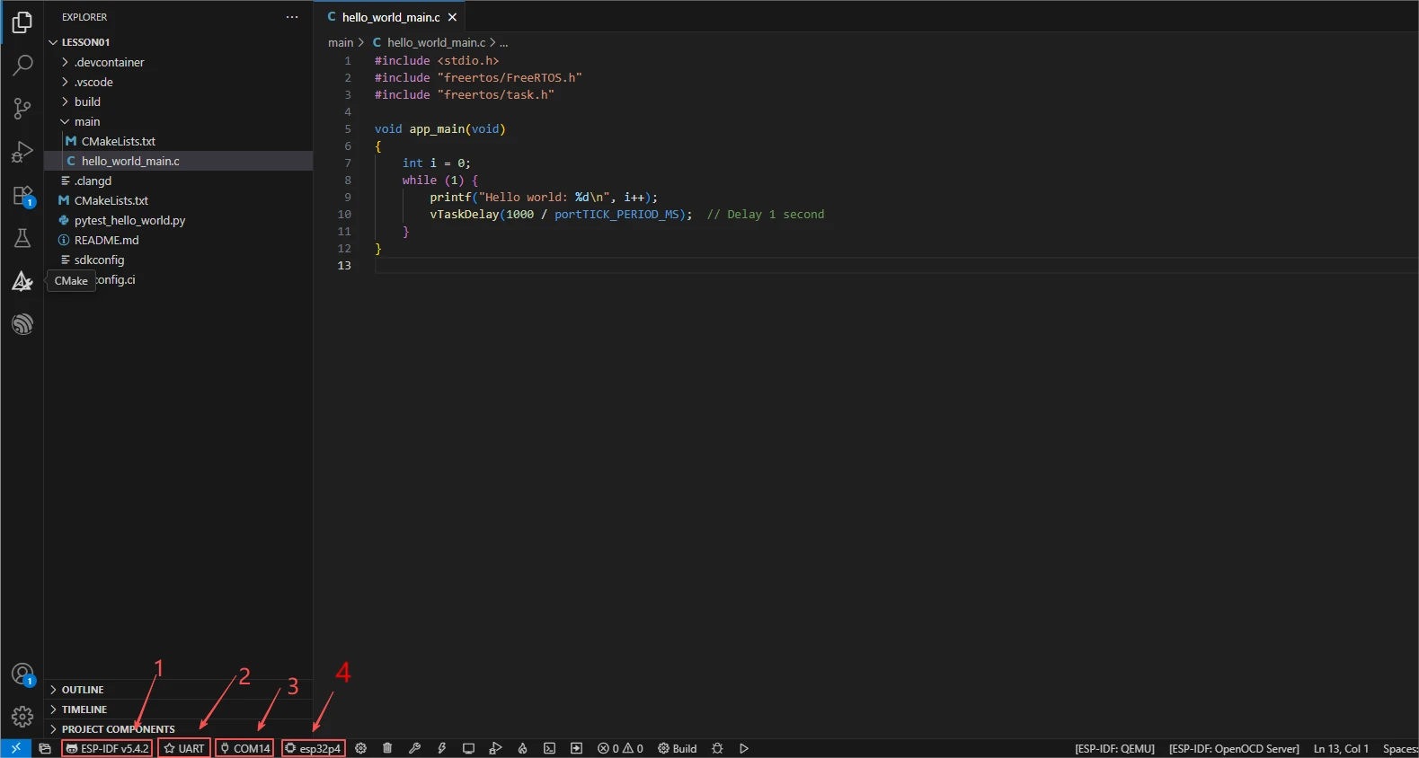
First, select the code runtime environment ESP-IDF v5.5.4, set the flashing method to UART, and then select the serial port that corresponds to the development board. Next, click Set Espressif Device Target in the ESP-IDF Extension panel and select esp32p4. After the setup is complete, the status bar should display ESP-IDF v5.5.4, UART, the required COM port, and ESP32-P4.
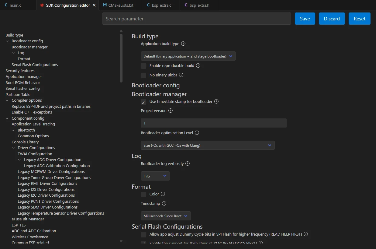
Click SDK Configuration Editor in the VS Code bottom status bar or the ESP-IDF extension panel, and wait for the configuration page to fully load before modifying parameters. If the page is still loading, do not perform Build immediately.

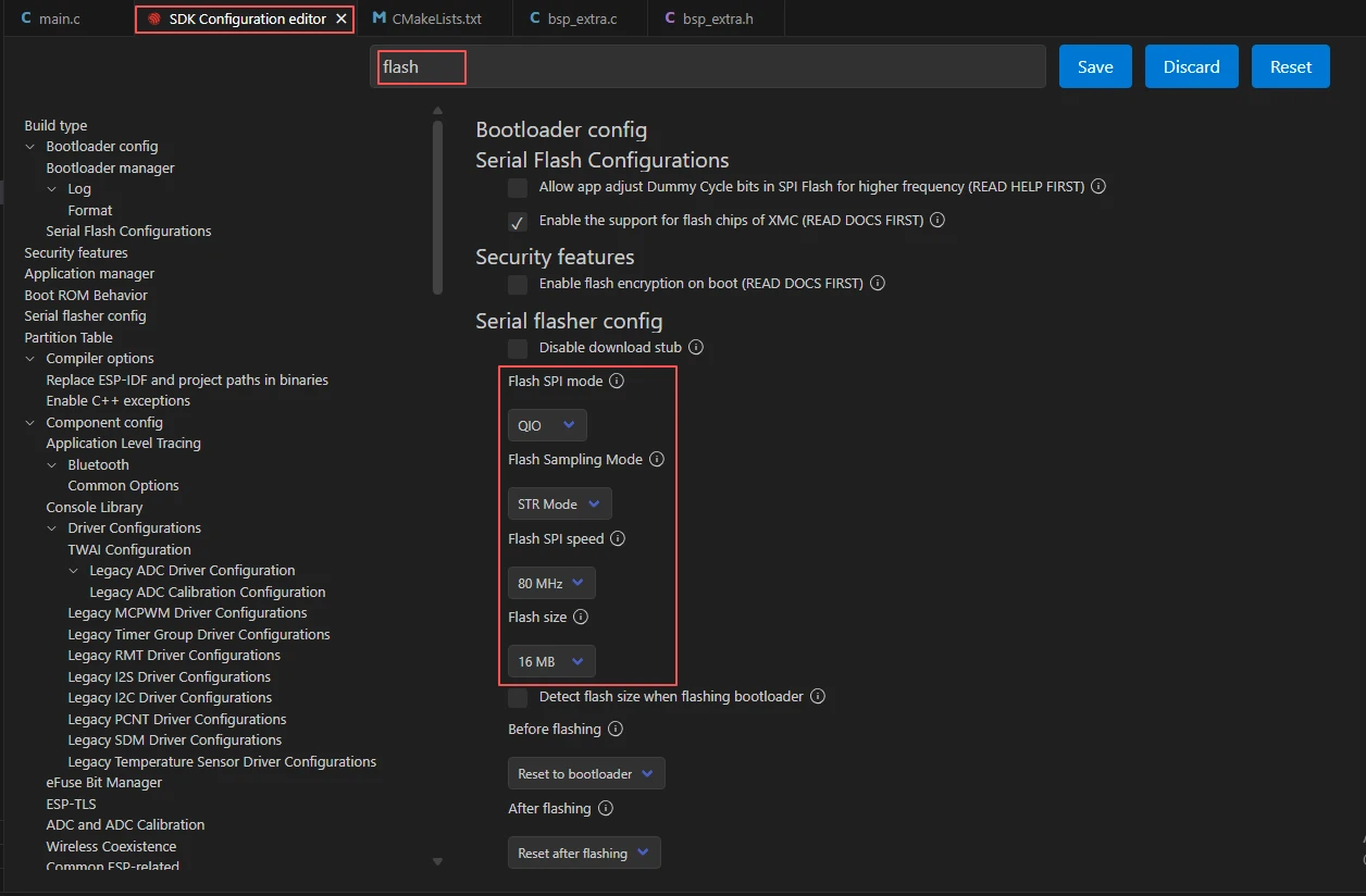
In the search box, type flash, and ensure Flash SPI mode: QIO; Flash Sampling Mode: STR Mode; Flash SPI speed: 80 MHz; Flash size: 16 MB. These parameters should match the Advance-P4 onboard Flash.
If you need to read or write long file names, enable long file name support for the FAT file system in the SDK Configuration Editor, and select the long file name working buffer method according to the project's needs; otherwise, read/write operations will fail when the file name is too long.
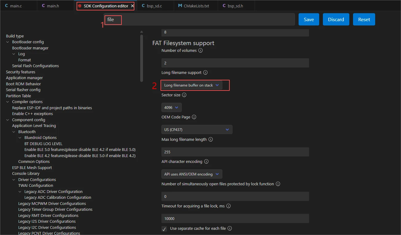
Click Save in the upper-right corner to save the Flash and FAT file system configuration, then proceed with compilation.
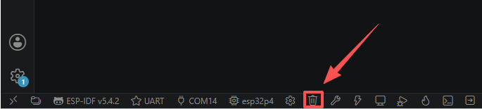
Click Full Clean to clear the cache left by the previous compilation. Perform this operation after the first compilation, when switching project configurations, or after modifying SDK parameters, to prevent old configurations from affecting the new build results.
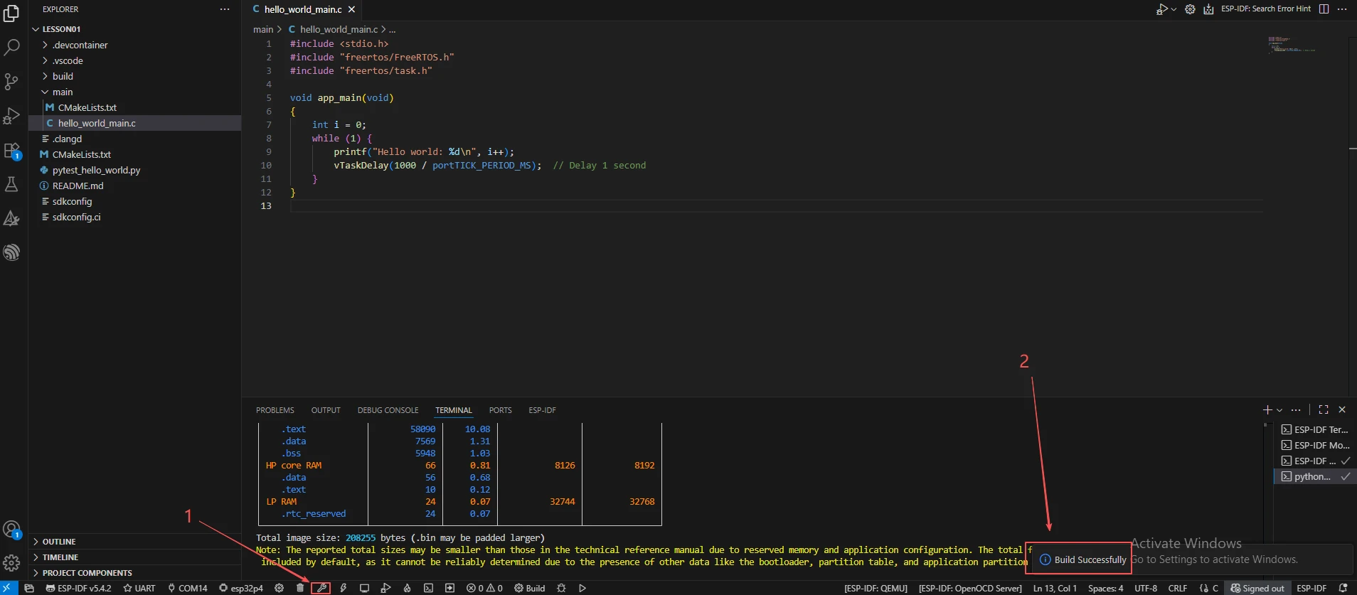
Click Build to compile the project. On success, the output shows Project build complete.
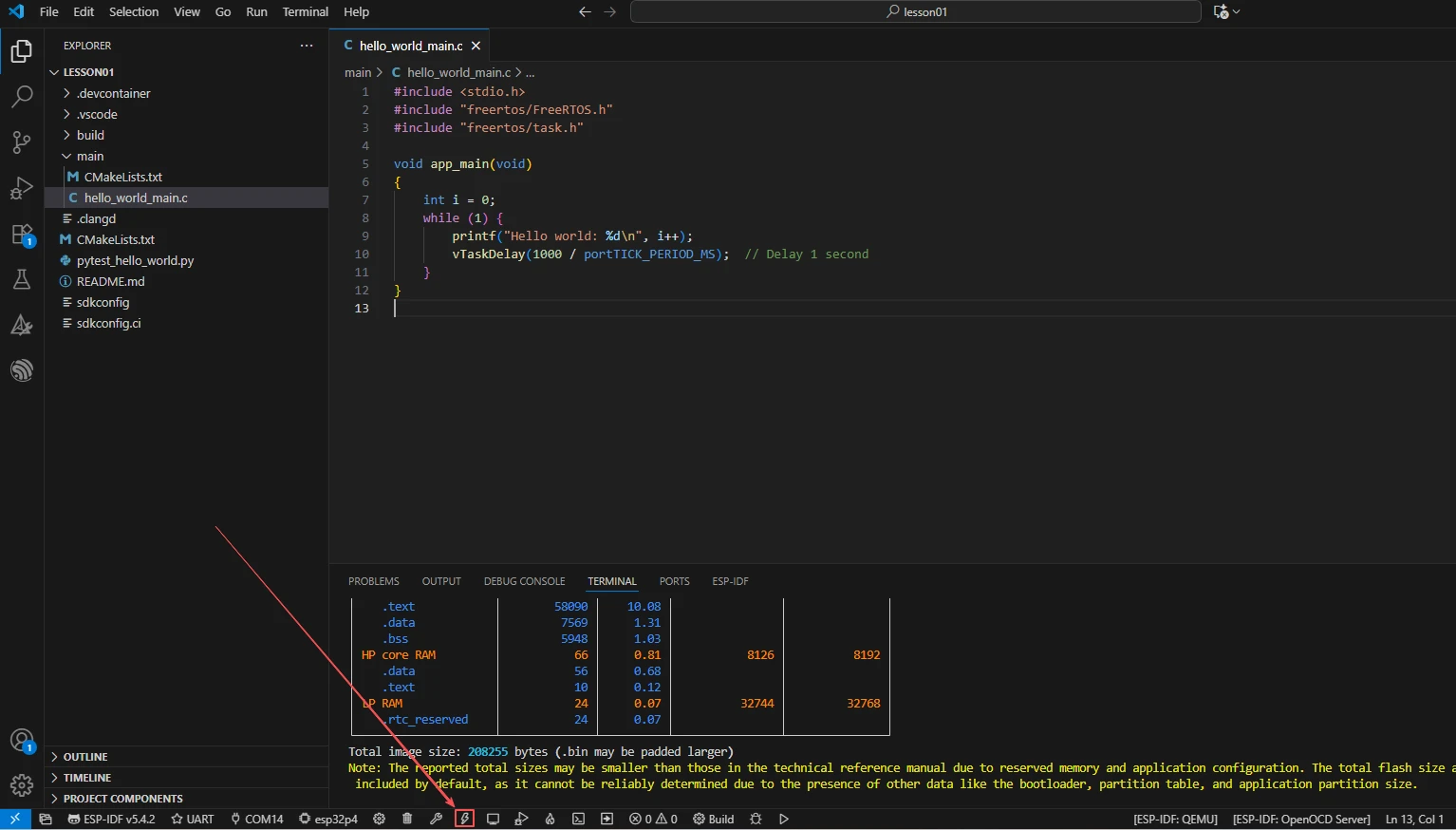
Confirm that the development board is connected to the computer via USB, click Select Port to Use to select the serial port, and click Flash to flash the firmware.
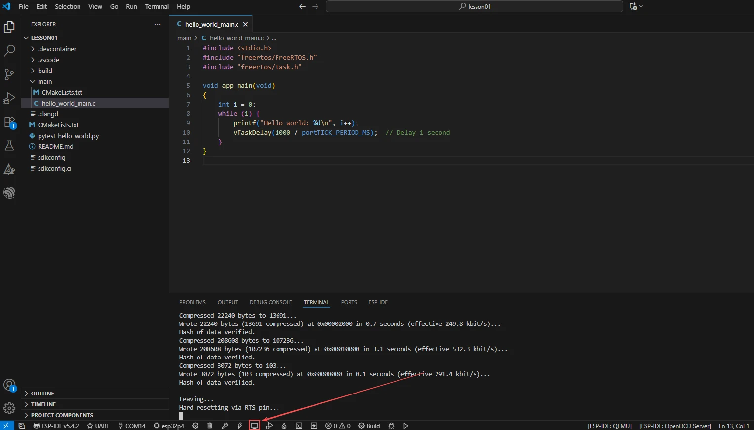
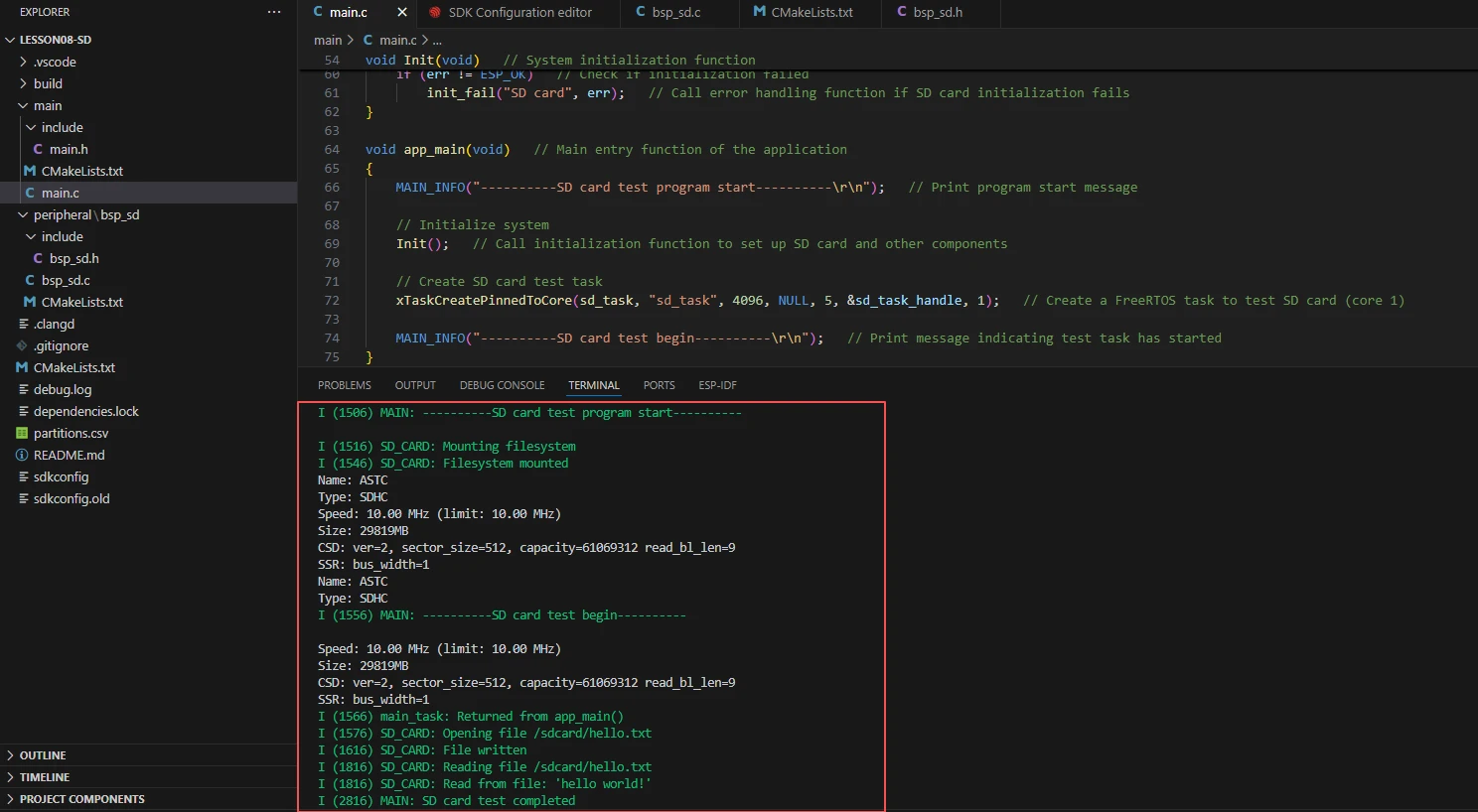
After flashing is complete, click Monitor to open the serial monitor; you should see the card information and the read/write logs. Press Ctrl + ] to exit the monitor.
After testing is complete, you can insert the SD card into a computer and confirm that hello.txt appears in the root directory with the content hello world!.
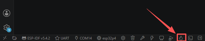
Finally, you can use the one-click operation button in the ESP-IDF status bar to sequentially perform compilation, flashing, and opening the serial monitor. Use this only after the project configuration, serial port, and code have all been confirmed correct; if you need to locate problems, you should still follow the steps above one by one.
5. Hardware Operation Steps
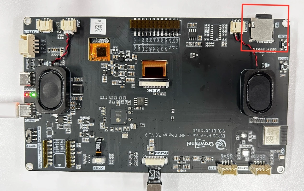
With the power off, insert the MicroSD card into the SD card slot (or adapter module) of the development board. Pay attention to the card orientation, with the gold contacts facing down.
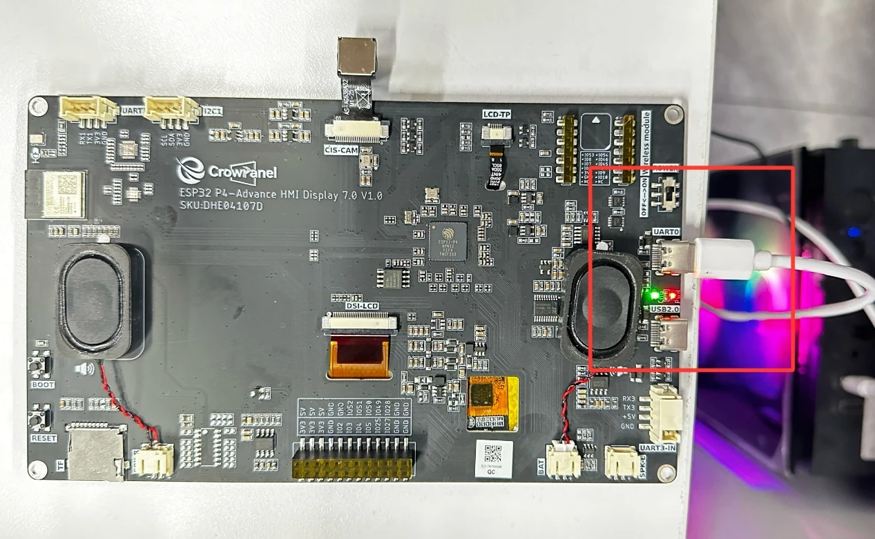
Use a USB data cable to connect the ESP32-P4 development board to the computer; the board's power indicator lights up.
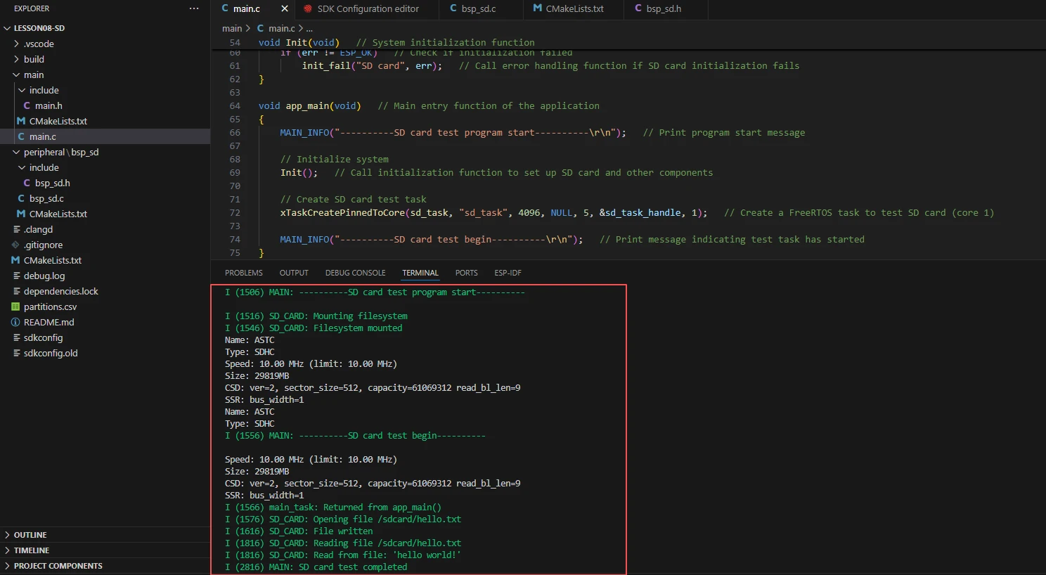
After flashing is complete and the board is reset, observe whether the serial port prints the card information (Name, Type, Size, Speed).
Observe whether the serial port sequentially prints File written and Read a line from file: 'hello world!', and confirm that read and write are consistent.
6. Key Code Explanation
sdmmc_host_t host = SDMMC_HOST_DEFAULT();
host.max_freq_khz = 10000;
sdmmc_slot_config_t slot_config = SDMMC_SLOT_CONFIG_DEFAULT();
slot_config.clk = GPIO_NUM_43;
slot_config.cmd = GPIO_NUM_44;
slot_config.d0 = GPIO_NUM_39;
slot_config.width = 1;
slot_config.flags |= SDMMC_SLOT_FLAG_INTERNAL_PULLUP;
err = esp_vfs_fat_sdmmc_mount(sd_mount_point, &host, &slot_config, &mount_config, &card);
This is the core of SD card initialization and mounting. host defines the SDMMC host parameters; max_freq_khz=10000 limits the clock to 10 MHz for better compatibility (high-speed cards may increase this, but some cards are unstable at high frequencies). slot_config specifies the GPIO pins and bus width (1-bit). esp_vfs_fat_sdmmc_mount mounts the FAT file system to /sdcard, after which standard C file APIs can be used for access. If the pins are misconfigured or the card is not inserted properly, mounting returns ESP_FAIL, and the serial port reports Failed to mount filesystem.
esp_vfs_fat_sdmmc_mount_config_t mount_config = {
    .format_if_mount_failed = false,
    .max_files = 5,
    .allocation_unit_size = 16 * 1024,
};
format_if_mount_failed=false means the file system will not be automatically formatted on mount failure (to protect data); max_files=5 limits the number of simultaneously open files; allocation_unit_size=16KB is the FAT cluster size. If changed to true, existing data on the card will be formatted and erased.
After mounting, the standard C fopen/fprintf/fclose can directly operate on SD card files, with the path prefix being the mount point /sdcard. The "w" mode overwrites an existing file. If fopen returns NULL, it is usually because mounting failed or the path is incorrect.
fgets reads a line (including the newline character), and then the \n is manually removed for clean logs. If no content can be read (returns NULL), it may be because the file is empty or was not written successfully.
7. Experimental Observations
After the program is flashed and reset, the serial monitor outputs:
I (xxx) MAIN: ----------SD card test program start----------
I (xxx) SD_CARD: Mounting filesystem
I (xxx) SD_CARD: Filesystem mounted
Name: SD64G, Type: SDHC, Size: 60906MB, Speed: 10000kHz
I (xxx) MAIN: ----------SD card test begin----------
I (xxx) SD_CARD: Opening file /sdcard/hello.txt
I (xxx) SD_CARD: File written
I (xxx) SD_CARD: Reading file /sdcard/hello.txt
I (xxx) SD_CARD: Read a line from file: 'hello world!'
I (xxx) MAIN: SD card test completed
The card information should correctly display the card name, type (SD/SDHC), capacity, and clock. The written and read content should be consistent. If mounting fails, the serial port reports Failed to mount filesystem; you should first check whether the SD card is inserted, whether the pins are correct, and whether it is in FAT32 format. If read and write are inconsistent, you should check the file path and the open mode.