Lesson10_I2C_DHT20: ESP32-P4 Temperature and Humidity Sensor DHT20
1. Course Introduction
This lesson uses ESP-IDF to read the DHT20 temperature and humidity sensor (I2C address 0x38) over I2C and display the real-time temperature and humidity data on the MIPI DSI screen. After the program is flashed, the development board powers on and resets, the I2C bus and DHT20 complete initialization, and the screen displays a black background with white text. The temperature and humidity values refresh once per second, and the serial monitor prints the measurement results synchronously.
This lesson serves as the foundation for the sensor course, integrating the I2C content from Lesson05 and the screen display content from Lesson07. Through this experiment, learners will complete end-to-end verification of the full chain covering I2C sensor initialization, CRC validation, data conversion, and LVGL real-time display.
2. Learning Objectives
- Be able to open the Lesson10 project in ESP-IDF and set the target chip to
esp32p4. - Be able to explain the DHT20 I2C communication flow (send measurement command → wait for busy bit → read data → CRC validation).
- Be able to explain the meaning of the formulas for converting DHT20 raw data into temperature and humidity.
- Be able to complete compilation and flashing, and observe whether the temperature and humidity values on the screen and in the serial monitor change in real time.
- Be able to determine whether sensor communication is normal based on whether the values are reasonable and whether the CRC passes.
3. Prerequisites
- Hardware: One CrowPanel Advanced 7 / 9 / 10.1-inch ESP32-P4 HMI AI Display development board, one USB Type-C data cable that supports data transfer, and one crowtail-dht20 temperature and humidity sensor.
- Compatibility note: The hardware and software code for the 7 / 9 / 10.1-inch development boards are interchangeable; only the board dimensions differ. Please select the appropriate model based on the display size and usage scenario.
- Software: VS Code, ESP-IDF Extension (ESP-IDF v5.5.4 or later).
- Project dependencies: Retain the
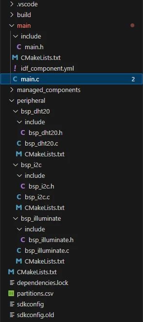
main/main.c,peripheral/bsp_dht20,peripheral/bsp_i2c, andperipheral/bsp_illuminatecomponents, as well as theesp_lcd_ek79007,esp_lvgl_port, andlvglmanaged components. - Configuration: Target chip
esp32p4; I2C port 0, SDA=GPIO45, SCL=GPIO46, 100 kHz; DHT20 address 0x38; LVGL font Montserrat 30.
Code download link:
4. Software Operation Steps
Open the ESP-IDF Extension panel in VS Code, click Open ESP-IDF Project, and select the Lesson10-Temperature_and_Humidity folder.
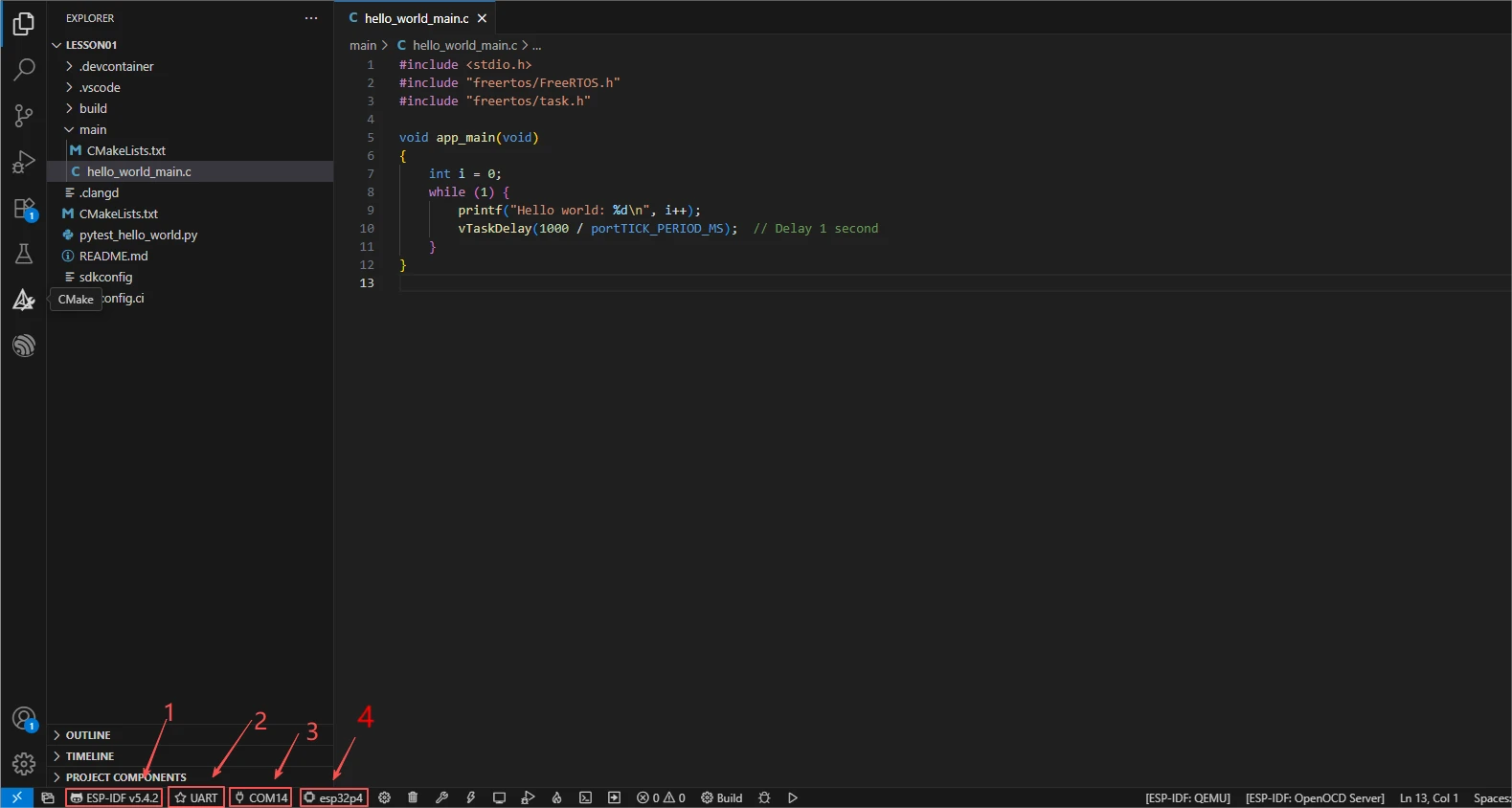
First, select the code runtime environment ESP-IDF v5.5.4, set the flashing method to UART, and then select the serial port that corresponds to your development board. Next, click Set Espressif Device Target in the ESP-IDF Extension panel and select esp32p4. After the settings are complete, the status bar should display ESP-IDF v5.5.4, UART, the required COM port, and ESP32-P4.
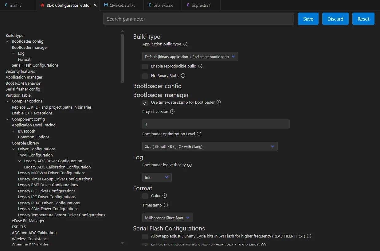
Click SDK Configuration Editor in the VS Code bottom status bar or in the ESP-IDF extension panel, and wait for the configuration page to fully load before modifying parameters. If the page is still loading, do not run Build immediately.

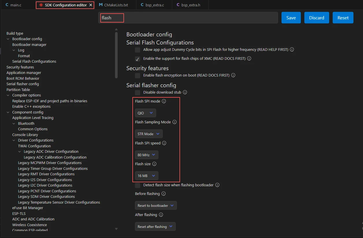
Enter flash in the search box and ensure that Flash SPI mode: QIO; Flash Sampling Mode: STR Mode; Flash SPI speed: 80 MHz; Flash size: 16 MB. These parameters should be consistent with the onboard Flash of the Advance-P4 board.
Next, refer to the "4. Software Operation Steps" in
Lesson07_Turn_on_the_Screento complete the detailed SDK configuration; the relevant configuration methods were covered in Lesson 7.Note: The LVGL font size used in this lesson is 30 points, so please modify it accordingly.
After verifying that the configuration is correct, click Save in the upper right corner; confirm that the changes have been saved, then run Build to compile.
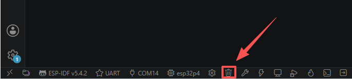
Click Full Clean to clear the cache left by the previous compilation. Perform this operation after the first compilation, after switching project configuration, or after modifying SDK parameters, to prevent old configuration from affecting the new compilation result.
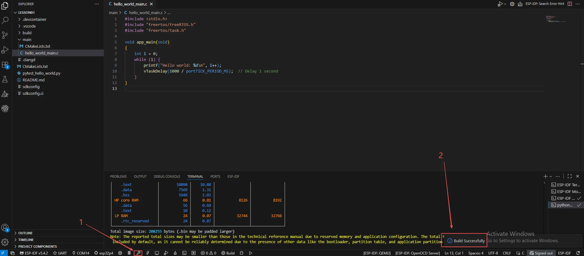
Click Build to compile the project. On success, the output shows Project build complete.
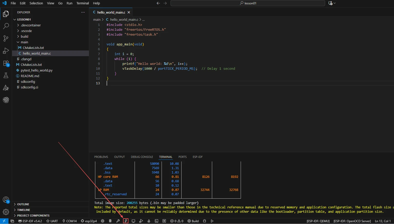
Confirm that the development board is connected to the computer via USB, click Select Port to Use to select the serial port, and click Flash to flash the firmware.
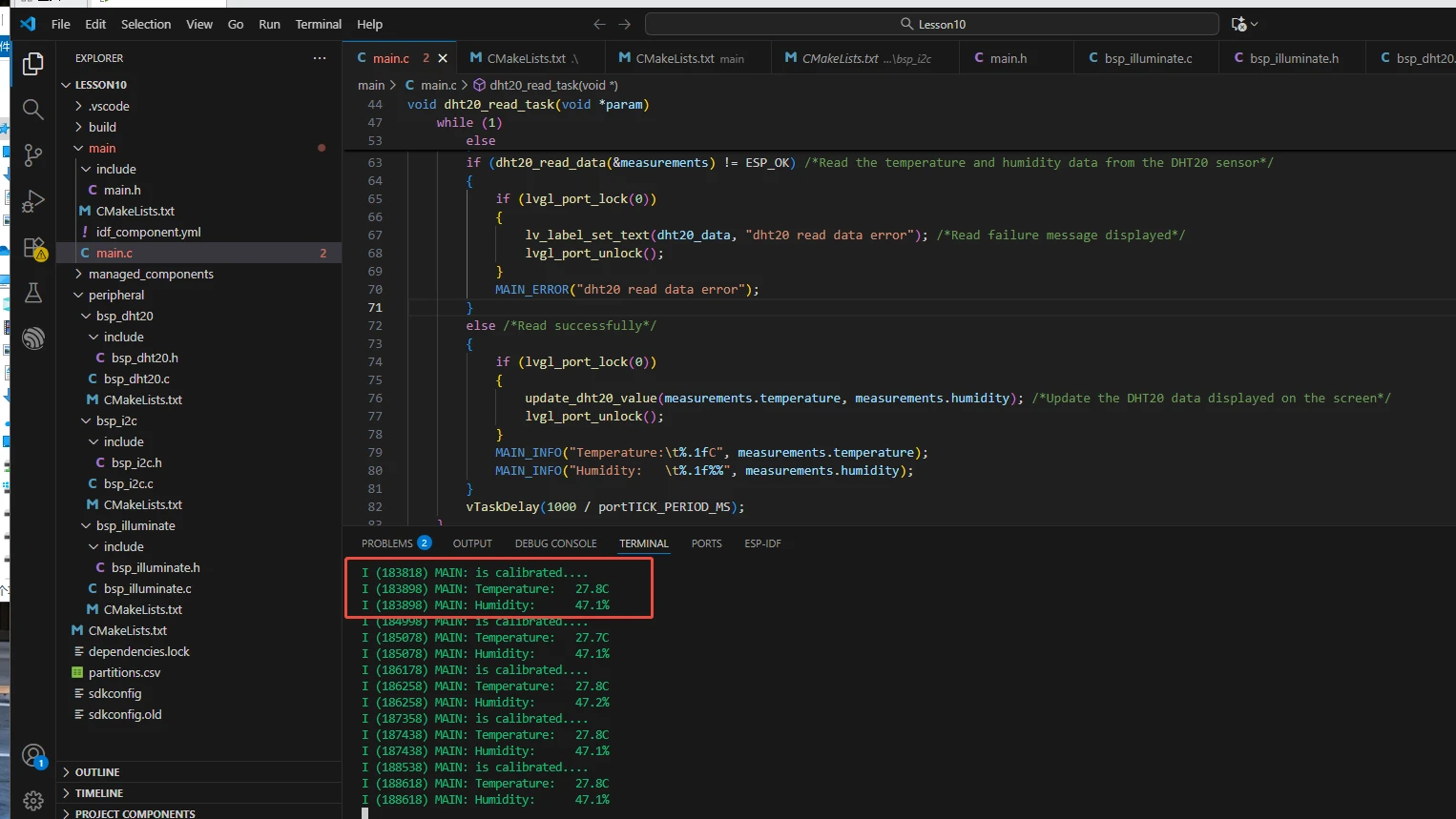
After flashing is complete, click Monitor to open the serial monitor; you should see the is calibrated.... log and the temperature and humidity value logs. Press Ctrl + ] to exit the monitor.
After flashing is complete, wait for the device to reset and observe whether the screen displays the temperature and humidity values.
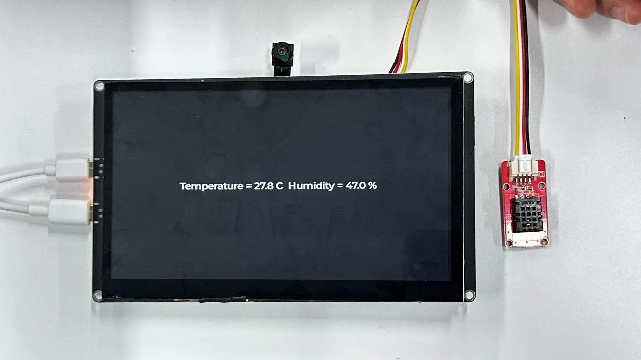
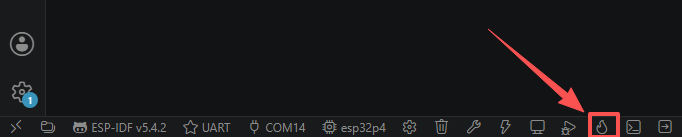
Finally, you can use the one-click operation button in the ESP-IDF status bar to run compilation, flashing, and opening the serial monitor in sequence. Use this only after the project configuration, serial port, and code have all been confirmed correct; if you need to locate problems, you should still follow the steps above and execute them one by one.
5. Hardware Operation Steps
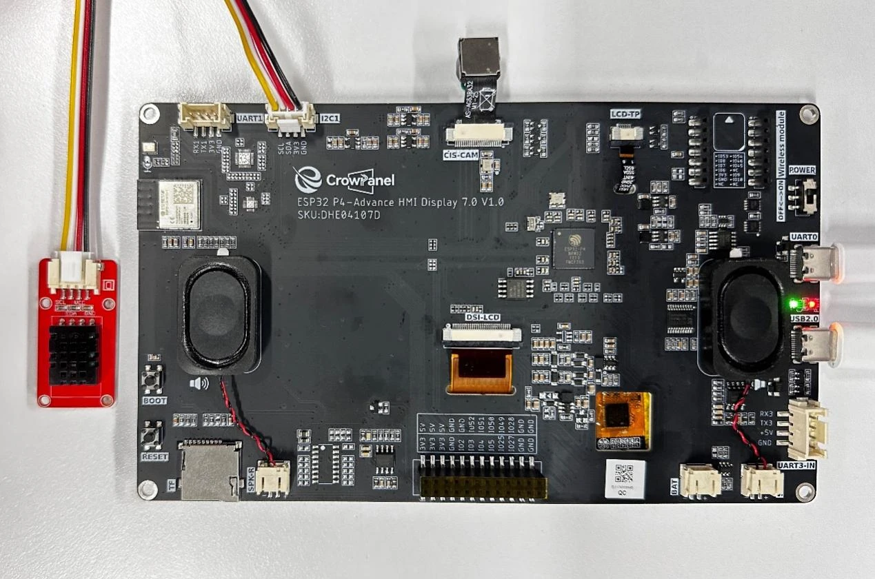
Connect the ESP32-P4 development board to the computer using a USB data cable. Confirm that the DHT20 sensor and the LCD flat cable are properly connected.
After flashing is complete and the board resets, observe whether the screen displays a black background with white temperature and humidity text.
Observe whether the temperature and humidity values on the screen refresh every second; the values should be within the room temperature range (for example, temperature 25.5°C, humidity 30.0%).
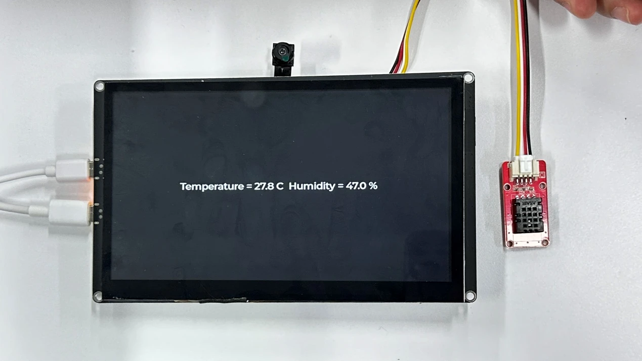
You can gently cover the DHT20 sensor with a finger (do not use sharp objects) and observe whether the temperature rises and the humidity changes, to verify sensor responsiveness.
6. Key Code Explanation
dht20_handle = i2c_dev_register(DHT20_I2C_ADDRESS);
if (dht20_reset_sensor() >= 255)
    err = ESP_FAIL;
DHT20 initialization: First register the device on the I2C bus (address 0x38), then reset the sensor until the status word is (status & 0x18) == 0x18 (indicating that it is calibrated). If the sensor is still not ready after more than 255 resets, return failure. If the address is written incorrectly or the sensor is not properly connected, registration will fail.
static uint8_t txbuf[3] = {0xAC, 0x33, 0x00};
err = i2c_write(dht20_handle, txbuf, 3);
vTaskDelay(80 / portTICK_PERIOD_MS);
Trigger measurement: Send the command 0xAC 0x33 0x00, then wait at least 80 ms (the minimum measurement time required by the datasheet). If the wait is less than 80 ms, the read data will be incomplete or all zeros.
while ((status_byte[0] >> 7) != 0) {
    if ((esp_timer_get_time() / 1000) - start_time >= DHT20_MEASURE_TIMEOUT)
        return ESP_ERR_TIMEOUT;
    portYIELD();
}
While measurement is in progress, bit 7 (the busy bit) of the status byte is 1, and you need to poll until it is cleared. A 1000 ms timeout is set to avoid an infinite loop. If the timeout check is removed, the task will hang permanently when the sensor malfunctions.
uint8_t get_crc = dht20_crc8(rxdata, 6);
if (rxdata[6] == get_crc) {
    ...
} else {
    return ESP_ERR_INVALID_CRC;
}
CRC-8 validation (polynomial 0x31) protects the first 6 bytes of data. The data is converted only if the CRC matches; otherwise, an error is returned. If the CRC check is removed, erroneous data caused by interference will be displayed as valid temperature and humidity.
data->humidity = (float)(raw_humid / 1048576.0f) * 100.0f;
data->temperature = (float)(raw_temp / 1048576.0f) * 200.0f - 50.0f;
The DHT20 uses a 20-bit ADC, with a full scale of 2^20 = 1048576. Humidity = raw_humid / 2^20 × 100%; Temperature = raw_temp / 2^20 × 200 − 50 (−50 to 150°C). If the formula is written incorrectly, the values will deviate completely from the normal range.
7. Experimental Observations
After the program is flashed and the board resets, the serial monitor outputs:
I (xxx) MAIN: ----------Demo version----------
I (xxx) DHT20: ...
I (xxx) MAIN: is calibrated....
I (xxx) MAIN: Temperature:   28.5C
I (xxx) MAIN: Humidity:      45.2%
I (xxx) MAIN: Temperature:   28.6C
I (xxx) MAIN: Humidity:      45.3%
Screen display: Black background, with centered white Montserrat 30-point font:
The values refresh every second. The temperature should be near room temperature (approximately 0 to 50°C), and the humidity is typically in the 30 to 70% range. During continuous operation, dht20 read data error or CRC Checksum failed should not appear. Covering the sensor gently with your hand should cause the temperature to rise slowly. If the values are all zeros or remain fixed, you should first check the I2C wiring and address; if CRC failures occur frequently, you should check the I2C pull-up resistors and bus interference.