Lesson11_I2S_Mic_Playback: ESP32-P4 Audio Recording and Playback
1. Course Introduction
In this lesson, we use ESP-IDF to control a PDM microphone (I2S0) via the I2S driver to record 5 seconds of audio, and then play back the original sound through the I2S audio output (I2S1) and the amplifier. After the program is flashed, the development board resets on power-up and the microphone and audio output are initialized; the program automatically records 5 seconds of audio and immediately plays back the recorded audio through the speaker once recording finishes.
This lesson serves as the foundation of the audio series, introducing PDM microphone input and I2S audio output for the first time. Through this experiment, learners will complete verification of the full audio pipeline: PDM capture, SPIRAM buffering, mono-to-stereo conversion, amplifier control, and I2S playback.
2. Learning Objectives
- Be able to open the Lesson11 project in ESP-IDF and set the target chip to
esp32p4. - Be able to explain the differences between a PDM microphone and I2S audio output, along with their respective configuration essentials.
- Be able to explain the purpose and blocking behavior of
i2s_channel_read/i2s_channel_write. - Be able to complete compilation and flashing, and hear the playback of the 5-second recording.
- Be able to determine whether the microphone and audio link are functioning properly based on the presence of recording logs and playback sound.
3. Prerequisites
- Hardware: One CrowPanel Advanced 7 / 9 / 10.1-inch ESP32-P4 HMI AI Display development board (with onboard PDM microphone, I2S audio output, amplifier, and speaker), and one USB Type-C data cable that supports data transfer.
- Compatibility note: The 7-, 9-, and 10.1-inch development boards share identical hardware and software code; only the board size differs. Please select the appropriate model based on the display size and usage scenario.
- Software: VS Code, ESP-IDF Extension (ESP-IDF v5.5.4 or later).
- Project dependencies: Keep the
main/main.c,peripheral/bsp_mic, andperipheral/bsp_audiocomponents. - Configuration: Target chip
esp32p4; PDM microphone I2S0 (CLK=GPIO24, DIN=GPIO26, 16 kHz mono); audio output I2S1 (BCLK=GPIO22, LRCLK=GPIO21, SDATA=GPIO23, 16 kHz stereo); amplifier control GPIO30 (active low); PSRAM used for recording buffer.
Code download link:
4. Software Operation Steps
Open the ESP-IDF Extension panel in VS Code, click Open ESP-IDF Project, and select the Lesson11-Playback_After_Recording folder.

First, select the code execution environment ESP-IDF v5.5.4, set the flashing method to UART, and then select the serial port that corresponds to the development board. Next, click Set Espressif Device Target in the ESP-IDF Extension panel and select esp32p4. After the configuration is complete, the status bar should display ESP-IDF v5.5.4, UART, the required COM port, and ESP32-P4.
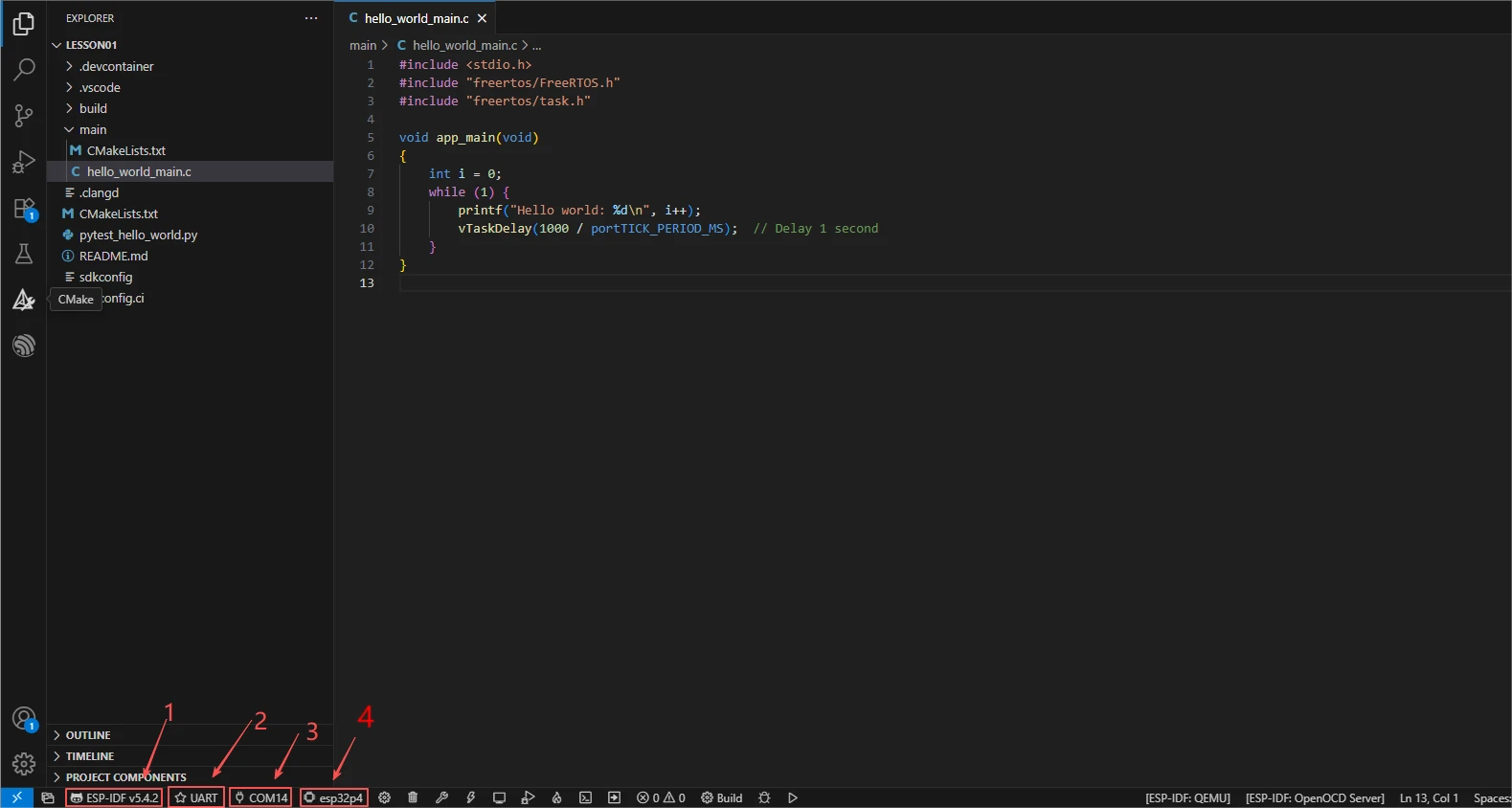
Click SDK Configuration Editor in the VS Code bottom status bar or the ESP-IDF extension panel, and wait for the configuration page to load completely before modifying parameters. If the page is still loading, do not run Build immediately.


Enter flash in the search box and ensure Flash SPI mode: QIO; Flash Sampling Mode: STR Mode; Flash SPI speed: 80 MHz; Flash size: 16 MB. These parameters should match the onboard Flash of the Advance-P4 board.
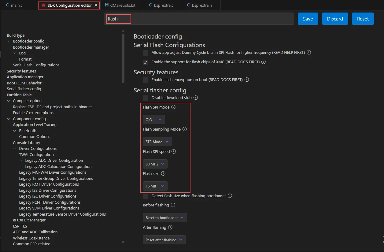
Then refer to "4. Software Operation Steps" in
Lesson07_Turn_on_the_Screento complete the detailed SDK configuration; the relevant configuration methods were covered in Lesson 7.
After verifying the configuration is correct, click Save in the top-right corner; confirm that the changes have been saved, then run Build to compile.
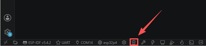
Click Full Clean to clear the cache left over from the previous build. Performing this after the first build, after switching project configurations, or after modifying SDK parameters helps prevent old configurations from affecting new build results.
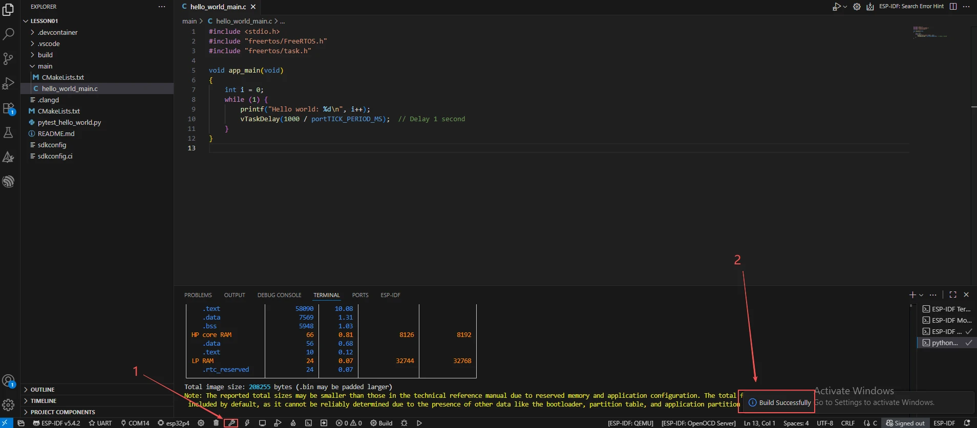
Click Build to compile the project. On success, the output will show Project build complete.
Confirm that the development board is connected to the computer via USB, click Select Port to Use to choose the serial port, then click Flash to flash the firmware.
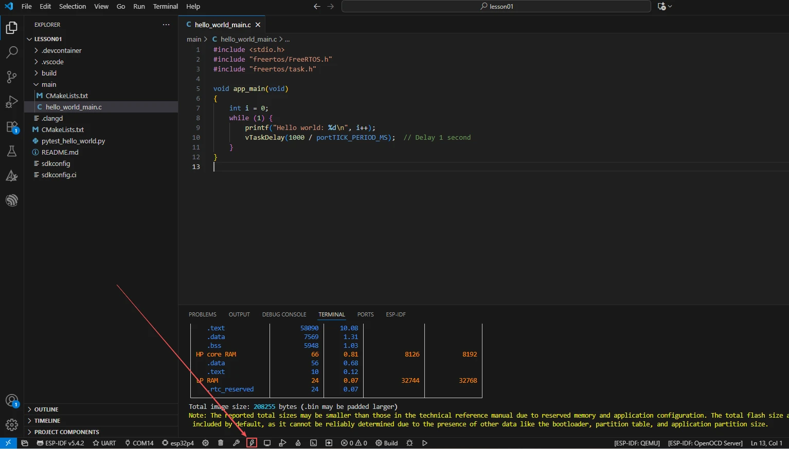
After flashing is complete, click Monitor to open the serial monitor; you should see recording and playback logs. Press Ctrl + ] to exit the monitor.
After flashing, the program automatically starts recording; speak toward the microphone for 5 seconds and wait for playback.
To hear sound playback, a speaker must be connected.
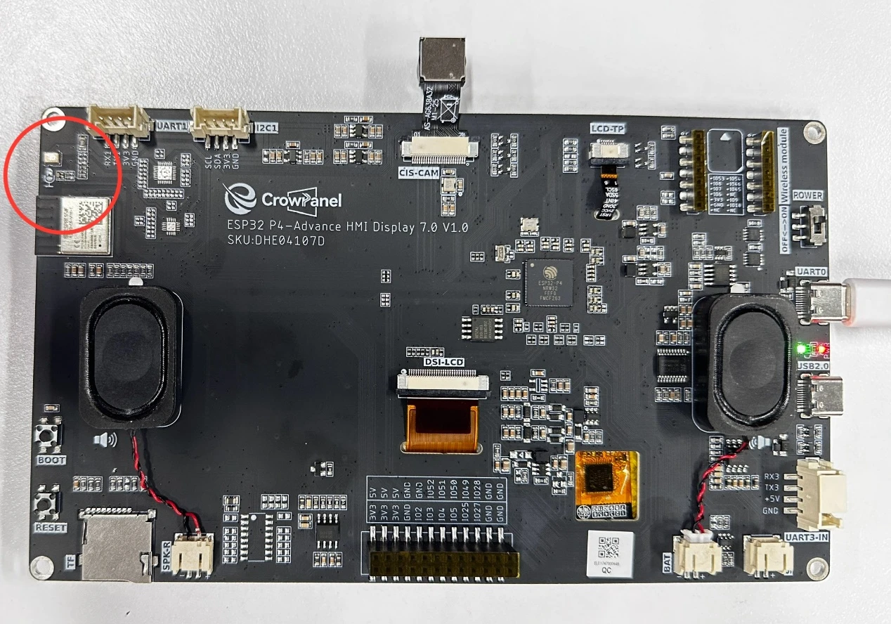
Finally, you can use the one-click operation button in the ESP-IDF status bar to run compilation, flashing, and opening the serial monitor in sequence. Use this only after the project configuration, serial port, and code have all been verified; if you need to troubleshoot, you should still follow the steps above one by one.

5. Hardware Operation Steps
Connect the ESP32-P4 development board to the computer using a USB data cable. Confirm that the speaker and microphone are correctly wired.
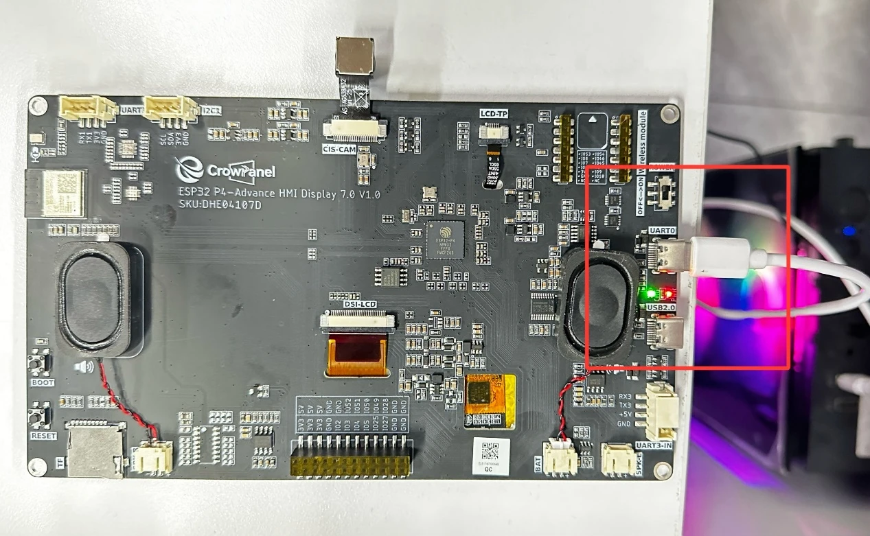
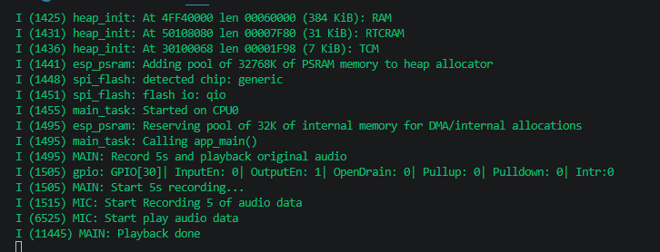
After flashing and reset, observe whether the serial port prints Start 5s recording..., and speak toward the microphone at this time.
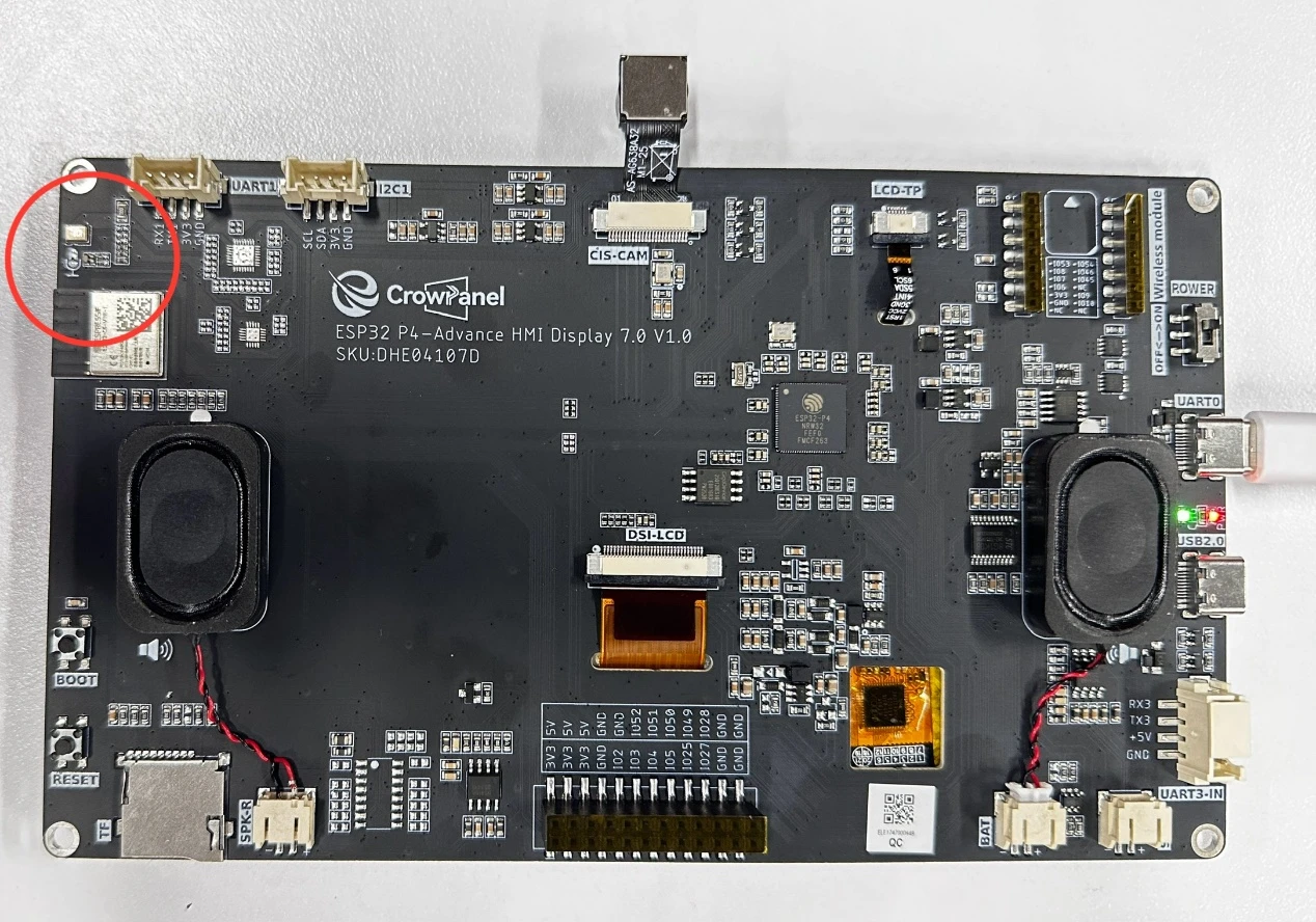
After 5 seconds of recording, observe whether the serial port prints Start play audio data; the speaker should play the audio that was just recorded.

After playback ends, observe whether the serial port prints Playback done to confirm that the entire process is complete.
6. Key Code Explanation
i2s_pdm_rx_config_t pdm_rx_cfg = {
    .clk_cfg = { .sample_rate_hz = 16000, .dn_sample_mode = I2S_PDM_DSR_8S, ... },
    .slot_cfg = { .slot_mode = I2S_SLOT_MODE_MONO, .hp_en = true, .hp_cut_off_freq_hz = 35.5, ... },
    .gpio_cfg = { .clk = MIC_GPIO_CLK, .din = MIC_GPIO_SDIN2, ... },
};
PDM microphone configuration: 16 kHz sample rate, 8× downsampling (the raw PDM rate is far higher than 16 kHz and must be downsampled); mono; high-pass filter enabled (cutoff frequency 35.5 Hz) to remove DC offset. If the pins are misconfigured or the sample rate does not match, the recording will be all noise or silent.

A 5-second, 16 kHz, mono, 16-bit recording requires about 160 KB, allocated in SPIRAM rather than internal RAM. If a regular malloc is used, the internal RAM may be insufficient and cause allocation to fail.
data = read_buf[i] * 10;
if (data > 32767) data = 32767;
else if (data < -32768) data = -32768;
write_buf[j] = data;
write_buf[j + 1] = data;
The recording is mono while playback is stereo. Here, each sample is amplified by 10× and clamped to the int16 range (to prevent overflow distortion), then copied to both the left and right channels. If the clamping is removed, the overflowed values after amplification will produce harsh popping sounds.
set_Audio_ctrl(true);
err = i2s_channel_write(write_handle, write_buf, rec_size * 2, &bytes_write, portMAX_DELAY);
set_Audio_ctrl(false);
The amplifier is turned on before playback and turned off after playback. i2s_channel_write is a blocking call that returns only after all data has been written to the DMA. If the amplifier is not turned off after playback, there will be continuous background noise. The amplifier control is active low, so set_Audio_ctrl(true) actually writes a low level.
7. Experimental Observations
After the program is flashed and reset, the serial monitor outputs:
I (xxx) MAIN: Record 5s and playback original audio
I (xxx) MAIN: Start 5s recording...
I (xxx) MIC: Start Recording 5 of audio data
I (xxx) MIC: Start play audio data
I (xxx) MAIN: Playback done
Timeline: Recording begins immediately upon reset for 5 seconds (speak toward the microphone at this time). After recording finishes, the amplifier turns on and the speaker plays back these 5 seconds of audio; after playback ends, the amplifier turns off. The playback audio should be recognizable as what was spoken during recording, with moderate volume and no obvious distortion. If no logs appear during the recording phase, check the microphone I2S configuration; if there is no sound output, check the amplifier GPIO30 and the I2S output pins.