Lesson13_MIPI_CSI_Camera: ESP32-P4 Camera Real-Time Display
1. Course Introduction
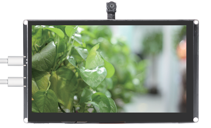
This lesson uses ESP-IDF to drive a MIPI CSI camera through the V4L2 video interface, configure the sensor via SCCB (I2C, SDA=GPIO12, SCL=GPIO13), capture RGB565 video frames, and display them in real time on a MIPI DSI screen. After the program is flashed, the development board powers on and resets; the LDO supplies power, the LCD lights up, and camera initialization completes. The screen then displays the camera-captured image in real time, and the image changes synchronously as the camera is moved.
This lesson is the core of the image acquisition course, introducing for the first time the MIPI CSI interface, the V4L2 video framework, and LVGL canvas real-time rendering. Through this experiment, learners will complete end-to-end verification of the full pipeline: CSI camera initialization, V4L2 buffer management, double-buffered streaming capture, and LVGL real-time display.
2. Learning Objectives
- Be able to open the Lesson13 project in ESP-IDF and set the target chip to
esp32p4. - Be able to explain the role of SCCB and MIPI CSI in a camera system.
- Be able to explain the V4L2 buffer flow: request (REQBUFS), query (QUERYBUF), enqueue (QBUF), and dequeue (DQBUF).
- Be able to complete compilation and flashing, and observe whether the camera image is displayed on the screen in real time.
- Be able to determine whether the CSI capture and display pipeline is functioning correctly based on whether the image changes as the camera is moved.
3. Prerequisites
- Hardware: One CrowPanel Advanced 7 / 9 / 10.1-inch ESP32-P4 HMI AI Display development board (with onboard MIPI CSI camera and EK79007 LCD), and one USB Type-C data cable that supports data transfer.
- Compatibility note: The hardware and software code for the 7 / 9 / 10.1-inch development boards are fully interchangeable; only the board size differs. Please select the appropriate model based on the display size and use case.
- Software: VS Code, ESP-IDF Extension (ESP-IDF v5.5.4 or later).
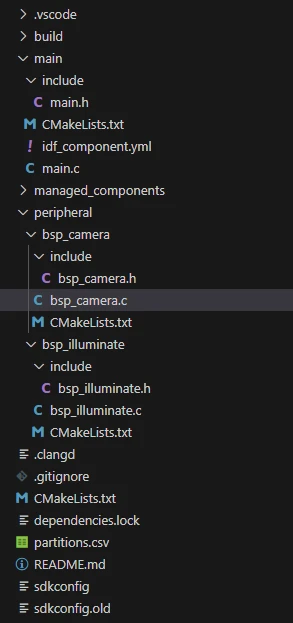
- Project dependencies: Keep the
main/main.c,peripheral/bsp_camera, andperipheral/bsp_illuminatecomponents, as well as theesp_lcd_ek79007,esp_lvgl_port,lvgl,esp_video_init, andesp_cam_sensormanaged components. - Configuration: Target chip
esp32p4; SCCB I2C port 1, SDA=GPIO12, SCL=GPIO13, 100 kHz; CSI RGB565; double-buffered SPIRAM; LVGL canvas 1024×600.
Code download link:
4. Software Operation Steps
Open the ESP-IDF Extension panel in VS Code, click Open ESP-IDF Project, and select the Lesson13-Camera_Real-Time folder.
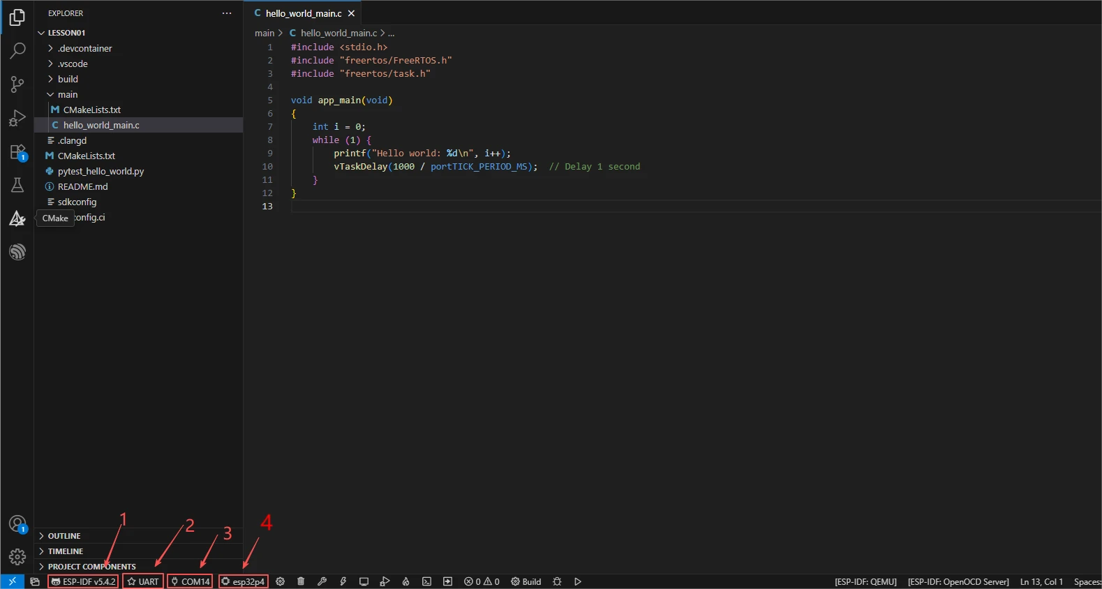
First select the code runtime environment ESP-IDF v5.5.4, set the flashing method to UART, and then select the serial port that actually corresponds to the development board. Next, in the ESP-IDF Extension panel, click Set Espressif Device Target and select esp32p4. After the configuration is complete, the status bar should display ESP-IDF v5.5.4, UART, the required COM port, and ESP32-P4.
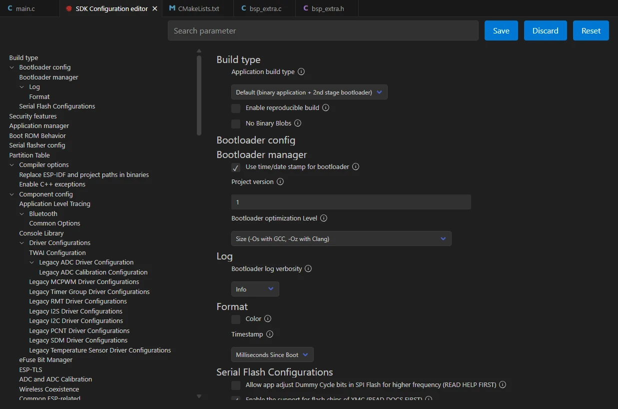
Click SDK Configuration Editor in the VS Code bottom status bar or the ESP-IDF extension panel, and wait for the configuration page to finish loading completely before modifying parameters. If the page is still loading, do not execute Build immediately.

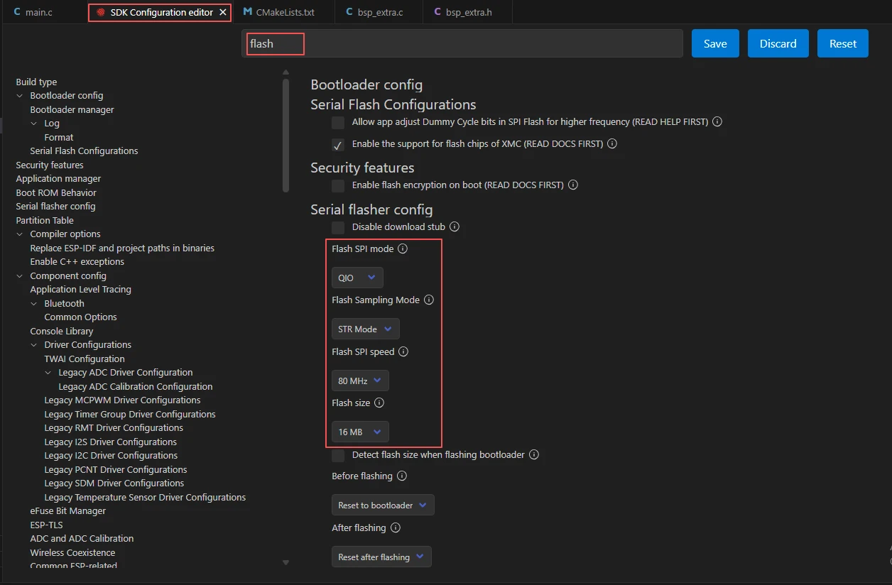
Enter flash in the search box and ensure Flash SPI mode: QIO; Flash Sampling Mode: STR Mode; Flash SPI speed: 80 MHz; Flash size: 16 MB. These parameters should match the onboard Flash of the Advance-P4 board.
Next, refer to "4. Software Operation Steps" in
Lesson07_Turn_on_the_Screento complete the detailed SDK configuration; the relevant configuration methods were covered in Lesson 7.
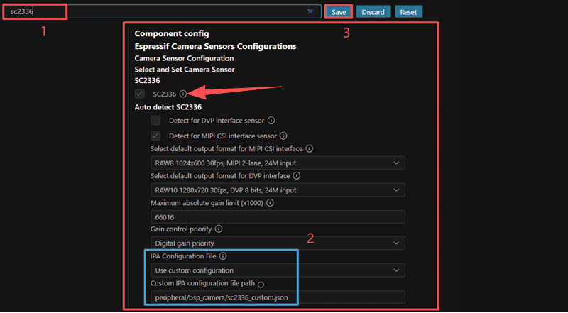
Configure the camera-related options as shown in the figure to ensure the camera works properly.
Please verify all parameters item by item; do not check only the options in the red box. Ensure the current configuration matches the image.
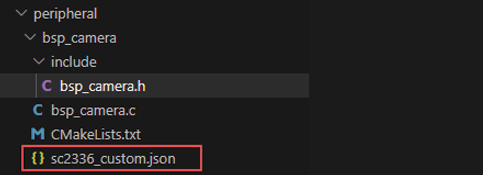
Use the sensor configuration file sc2336_custom.json provided by the project in the camera component directory. This configuration file contains the parameters required by this camera; it must be retained and correctly referenced in order for the camera image to display properly.
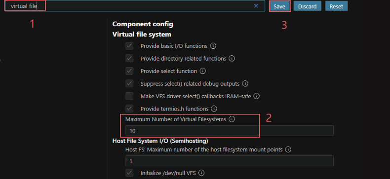
Search for virtual file and set Maximum Number of Virtual Filesystems to 10. This option determines the number of filesystems or device nodes the VFS framework can register simultaneously. This project not only uses V4L2 video device nodes such as /dev/video0, but may also use serial ports, logging, an SD card, or a Flash filesystem; increasing this value appropriately prevents device registration failures, failure to open the camera, or unstable system operation caused by insufficient VFS slots.
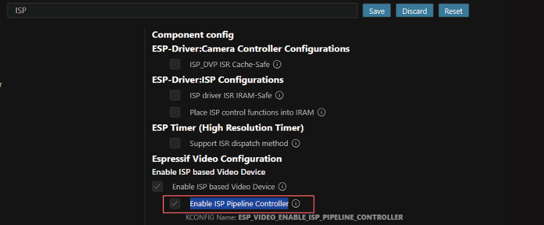
Search for ISP and enable Enable ISP based Video Device and Enable ISP Pipeline Controller as shown in the figure. Once enabled, the system will use the hardware ISP video device driver and create a dedicated isp_task background task that automatically reads statistics such as exposure and white balance and dynamically adjusts the camera or ISP parameters, thereby achieving more stable and natural color and brightness. This is the key configuration for the ESP32-P4 to obtain high-quality images when using MIPI cameras such as the SC2336.
After verifying the configuration is correct, click Save in the upper-right corner; confirm that the changes have been saved, then execute Build to compile.
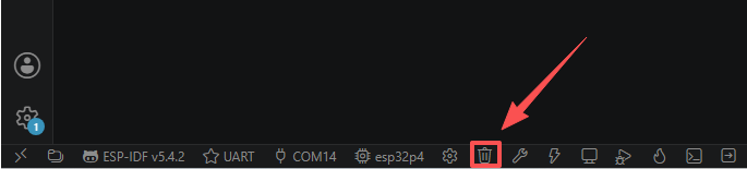
Click Full Clean to clear the cache left over from the previous compilation. Performing this operation after the first compilation, after switching project configurations, or after modifying SDK parameters avoids old configurations affecting the new build result.
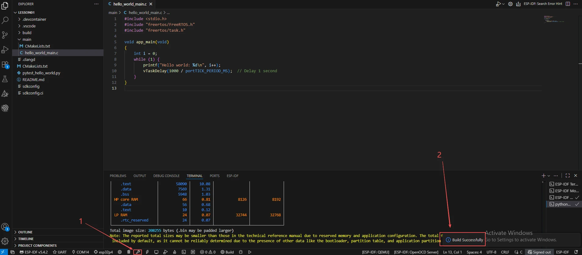
Click Build to compile the project. The first compilation will automatically download the video-related managed component; on success, it outputs Project build complete.
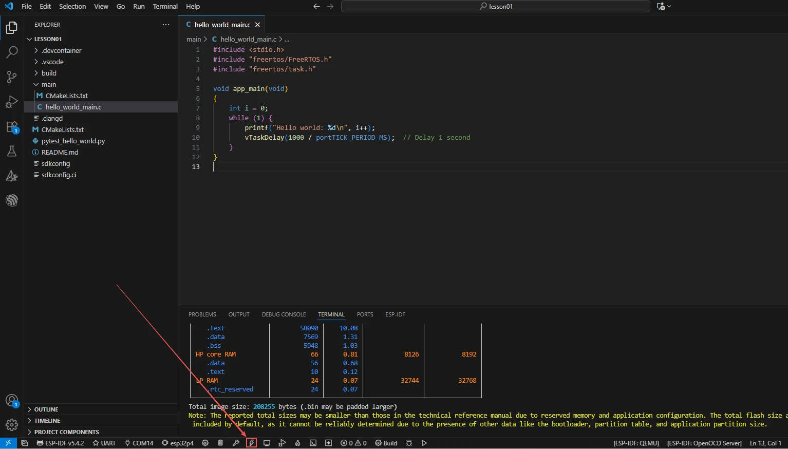
Confirm that the development board is connected to the computer via USB, click Select Port to Use to choose the serial port, and click Flash to flash the firmware.
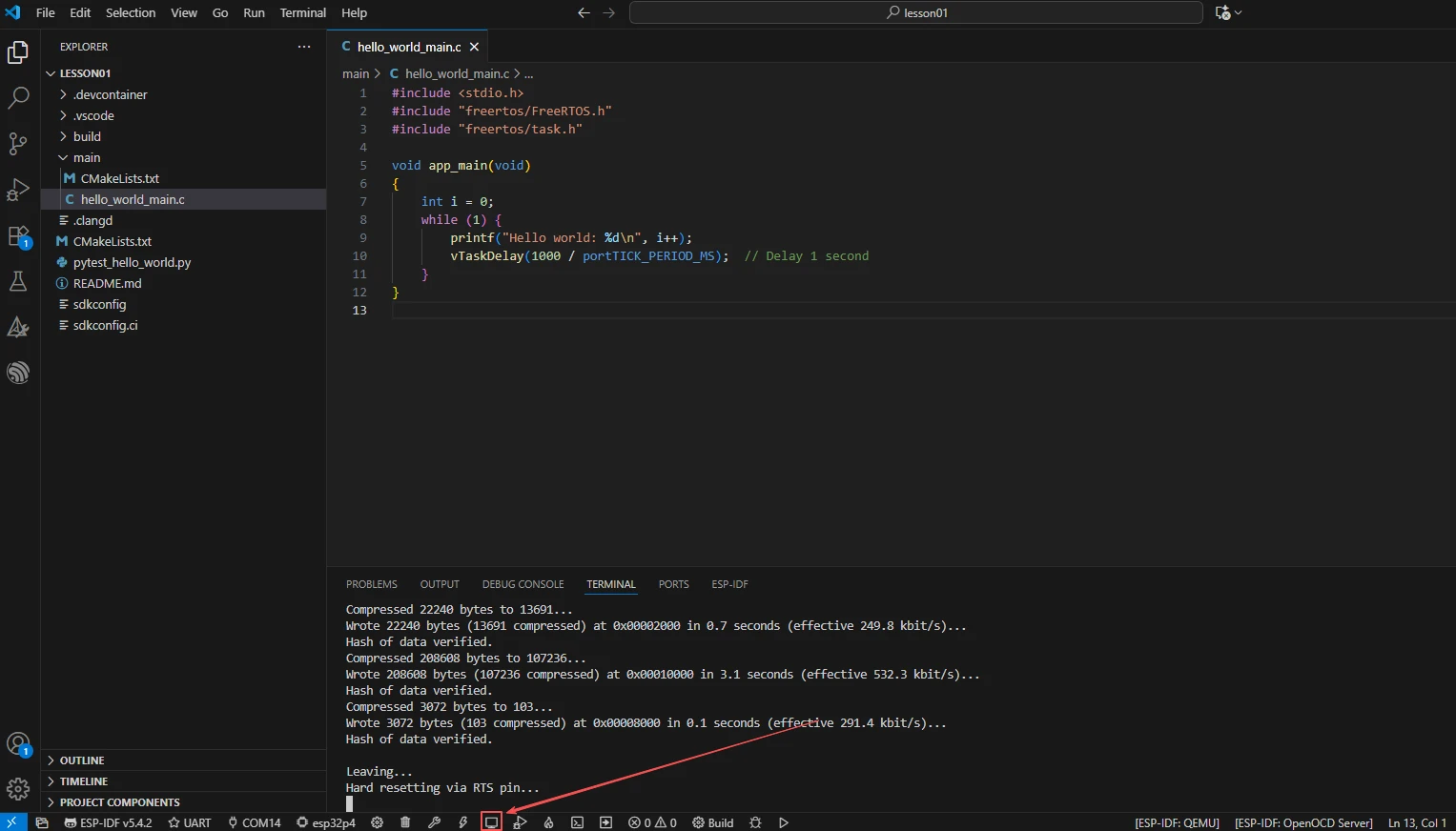
After flashing is complete, click Monitor to open the serial monitor; you should see camera capability query and stream startup logs. Press Ctrl + ] to exit the monitor.
After flashing is complete, wait for the device to reset and observe whether the screen displays the camera image in real time.
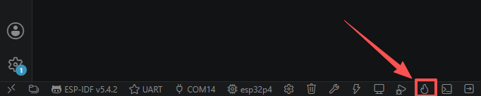
Finally, you can use the one-click operation button in the ESP-IDF status bar to continuously execute compilation, flashing, and opening the serial monitor. Use this only after the project configuration, serial port, and code have all been confirmed correct; if you need to locate a problem, you should still follow the steps above one by one.
5. Hardware Operation Steps
Connect the ESP32-P4 development board to the computer using a USB data cable. Confirm that the camera FPC cable and LCD cable are properly connected.
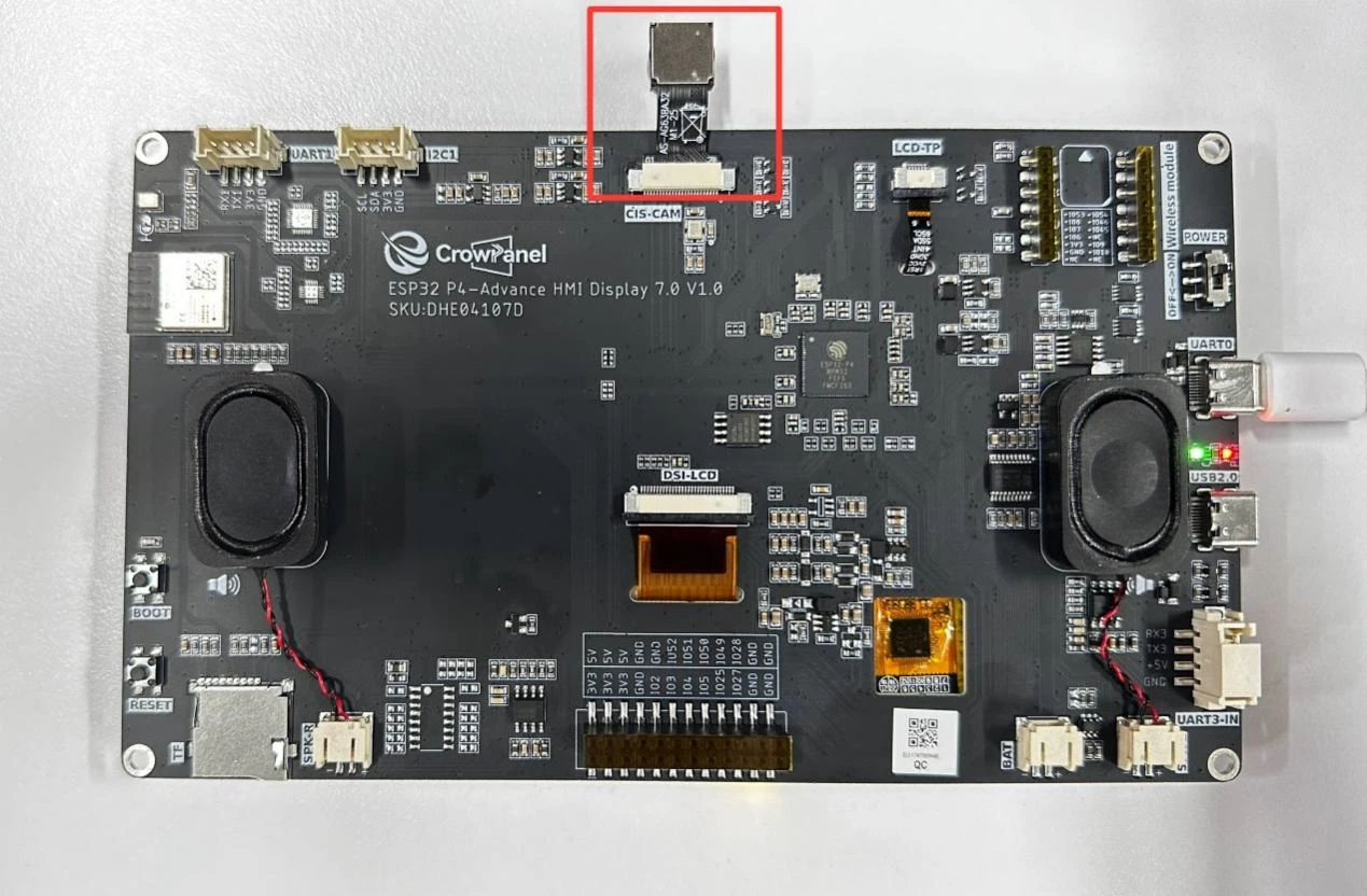
After flashing and reset, observe whether the screen backlight lights up and whether the LCD displays the camera image.
Slowly move the camera or wave your hand in front of the lens, and observe whether the screen image changes synchronously to confirm real-time performance.
Observe whether the image is smooth, free of artifacts or tearing, and has normal color without tinting, to confirm that the CSI capture and display pipeline is stable.
6. Key Code Explanation
i2c_master_bus_config_t sccb_conf = { .sda_io_num = SCCB_GPIO_SDA, .scl_io_num = SCCB_GPIO_SCL, ... };
err = i2c_new_master_bus(&sccb_conf, &sccb_bus_handle);
esp_video_init_config_t cam_config_ptr = { .csi = &csi_config, };
err = esp_video_init(&cam_config_ptr);
SCCB is the camera's control bus (essentially I2C), used to configure sensor registers (resolution, format, flip, etc.). esp_video_init initializes the MIPI CSI receiver and probes the sensor. If the SCCB pins are misconfigured, the sensor cannot be probed, and subsequent open calls will fail.
if (camera_format.fmt.pix.pixelformat != V4L2_PIX_FMT_RGB565) {
    struct v4l2_format format = { .fmt.pix.pixelformat = V4L2_PIX_FMT_RGB565, ... };
    ioctl(fd, VIDIOC_S_FMT, &format);
}
Force the sensor to output RGB565 format, consistent with the LCD and the LVGL canvas. If the format does not match (e.g., YUYV), the display will show artifacts or incorrect colors.
cam_buffer[i] = heap_caps_aligned_alloc(cache_line_size, ..., MALLOC_CAP_SPIRAM);
camera_video_set_bufs(camera_video_id, 2);
Allocate cache-aligned frame buffers in SPIRAM, then call camera_video_set_bufs(video_fd, 2) to configure two V4L2 buffers. Double buffering allows capture and display to run in parallel: while one frame is being captured, the other is being displayed. Cache alignment is a DMA requirement; misalignment will cause data errors.
err = video_receive_video_frame(video_fd);
video_operation_video_frame(video_fd);
err = video_free_video_frame(video_fd);
Core loop of streaming capture: dequeue a frame (DQBUF) → invoke the callback to draw it onto the LVGL canvas → re-enqueue it (QBUF) so the device can continue filling it. This loop runs continuously in a background task. If QBUF is forgotten, acquisition will stop once the buffer pool is exhausted.
lv_canvas_set_buffer(camera_obj, camera_buf, camera_buf_hes, camera_buf_ves, LV_IMG_CF_TRUE_COLOR);
lv_refr_now(NULL);
Set the just-captured frame buffer directly as the LVGL canvas display buffer and force an immediate refresh. LV_IMG_CF_TRUE_COLOR indicates that the pixels are raw RGB pixels and require no decoding. This is zero-copy display—camera data is sent straight to the display without passing through the LVGL drawing pipeline.
7. Experimental Observations
After the program is flashed and reset, the serial monitor outputs:
I (xxx) MAIN: ----------Camera task----------
I (xxx) CAMERA: Initializing SCCB Bus.......
I (xxx) CAMERA: version: ...
I (xxx) CAMERA: driver:  ...
I (xxx) CAMERA: card:    ...
I (xxx) CAMERA: width=1024 height=600
I (xxx) CAMERA: app_video_open successful
I (xxx) CAMERA: Video Stream Start
I (xxx) MAIN: ----------The screen is displaying.----------
Screen behavior: The backlight lights up and displays the camera-captured image in real time. The image should be smooth, with normal colors and no noticeable tearing. When the camera is moved, the image changes synchronously with extremely low latency (virtually imperceptible to the naked eye). If the screen is entirely black or shows artifacts, check the camera FPC cable and SCCB pins. If the image is frozen, check whether the streaming task has started and whether the buffers are correctly enqueued.