Lesson14_SPI_SX1262_LoRa: ESP32-P4 SX1262 LoRa Transmit and Receive Communication
1. Course Introduction
In this lesson, we use ESP-IDF to drive the SX1262 LoRa module through the SPI interface and the RadioLib library, implementing point-to-point wireless data transmission and reception. The lesson includes two projects—a transmitter (TX) and a receiver (RX)—requiring two ESP32-P4 development boards paired for use. The TX board sends an incrementing counter data packet TX_Hello World:N every second and displays the count on the screen; after receiving the packet, the RX board displays the RX_Hello World:N count along with RSSI and SNR values on the screen.
After flashing the program, the TX board's screen shows a white background with black TX_Hello World:N text, and the count increments every second; the RX board's screen displays the RX_Hello World:N count incrementing with each reception and shows RSSI and SNR in real time. Through this experiment, learners will complete the full wireless communication link validation covering SPI bus configuration, SX1262 LoRa initialization, interrupt-driven transmit/receive, and real-time LVGL display.
2. Learning Objectives
- Be able to open the TX and RX projects of Lesson14 in ESP-IDF and set the target chip to
esp32p4. - Be able to explain the SX1262 SPI connections (SCK/MISO/MOSI/NSS/IRQ/NRST/BUSY) and the function of each pin.
- Be able to explain the meaning of the LoRa parameters (frequency 915 MHz, BW 125 kHz, SF7, CR7).
- Be able to explain the working mechanism of interrupt-driven transmit/receive (setPacketSentAction/setPacketReceivedAction).
- Be able to complete compilation and flashing of both boards, and observe the TX count incrementing, the RX count incrementing with reception, and real-time RSSI/SNR updates.
3. What You Need
- Hardware: Two CrowPanel Advanced 7 / 9 / 10.1-inch ESP32-P4 HMI AI Display development boards; two USB Type-C data cables that support data transfer; two SX1262 LoRa modules, with one module connected to each development board.
- Compatibility note: The 7 / 9 / 10.1-inch development boards share the same hardware and software code, differing only in board size; please select the appropriate model based on display size and use case.
- Software: VS Code, ESP-IDF Extension (ESP-IDF v5.5.4 or later).
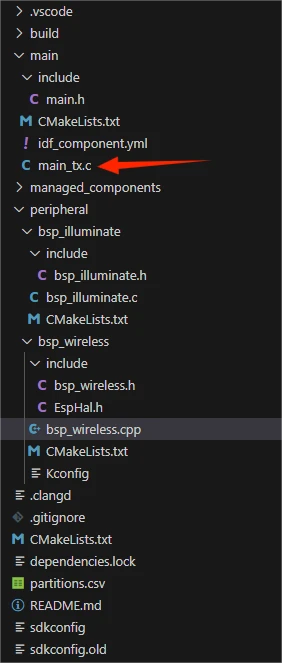
- Project dependencies: Keep
main/main_tx.cfor the TX project,main/main_rx.cfor the RX project, along with theperipheral/bsp_wirelessandperipheral/bsp_illuminatecomponents and theRadioLibmanaged component. - Configuration: target chip
esp32p4; SPI3, SCK=GPIO8, MISO=GPIO7, MOSI=GPIO6, NSS=GPIO10, IRQ=GPIO27, NRST=GPIO28, BUSY=GPIO9; LoRa 915 MHz / 125 kHz / SF7 / CR7 / 22 dBm.
Code download link:
4. Software Operation Steps
Open the ESP-IDF Extension panel in VS Code, click Open ESP-IDF Project, and select the Lesson14_TX_SX1262_Wireless_Module folder (transmitter).
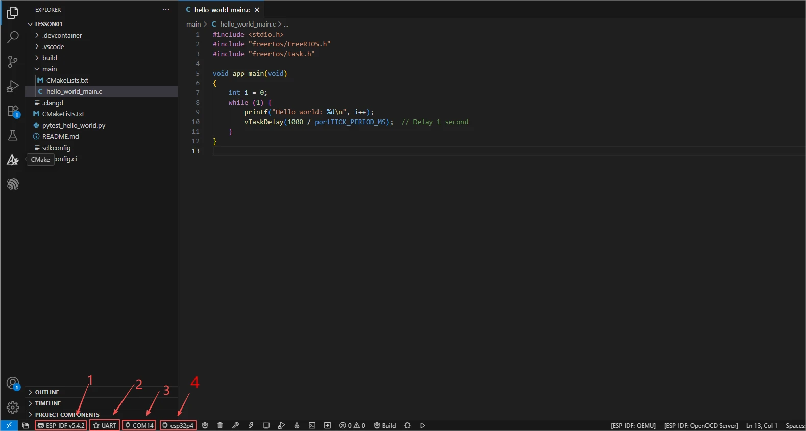
First, select the code execution environment ESP-IDF v5.5.4, set the flashing method to UART, then select the serial port corresponding to the development board. Next, click Set Espressif Device Target in the ESP-IDF Extension panel and select esp32p4. After the configuration is complete, the status bar should display ESP-IDF v5.5.4, UART, the required COM port, and ESP32-P4.
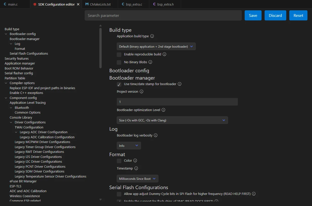
Click SDK Configuration Editor in the VS Code bottom status bar or the ESP-IDF extension panel, and wait for the configuration page to fully load before modifying parameters. If the page is still loading, do not run Build immediately.

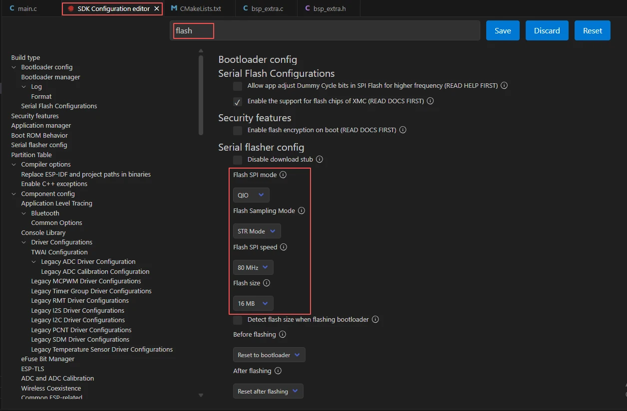
Enter flash in the search box and ensure Flash SPI mode: QIO; Flash Sampling Mode: STR Mode; Flash SPI speed: 80 MHz; Flash size: 16 MB. These parameters should match the onboard Flash of the Advance-P4 board.
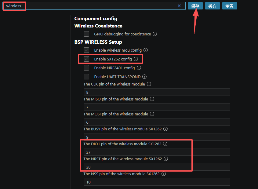
Enter wireless in the search box, check only Enable SX1262 config, and disable the wireless module configurations not used in this lesson, such as nRF2401, ESP32-C6, and ESP32-H2. This setting must be completed separately for both the TX and RX projects.
Then refer to "4. Software Operation Steps" in
Lesson07_Turn_on_the_Screento complete the detailed SDK configuration; the relevant configuration methods were covered in Lesson 7.Note: The LVGL font size used in this lesson is 42 pt; please modify it accordingly.
After verifying the configuration is correct, click Save in the upper-right corner; confirm the changes are saved, then run Build to compile.
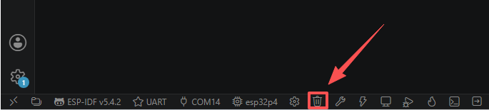
Click Full Clean to clear the cache left by the previous compilation. Run this operation after the first compilation, when switching project configurations, or after modifying SDK parameters, to prevent old configurations from affecting the new build result.
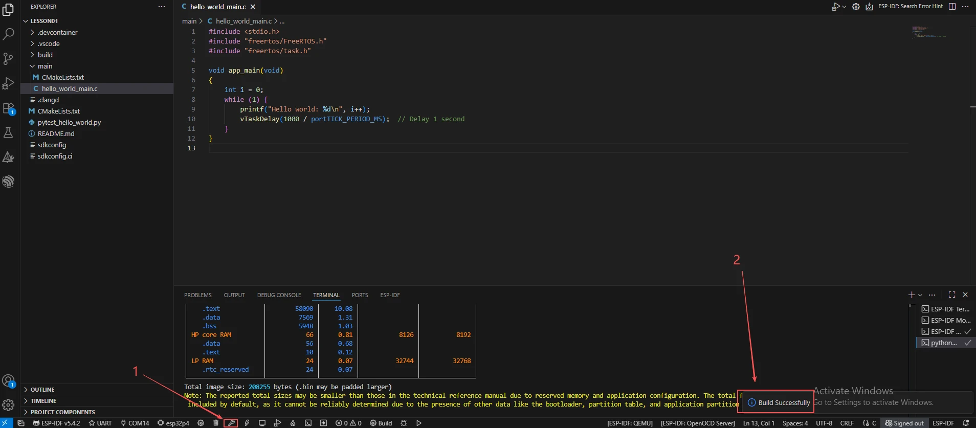
Click Build to compile the TX project. On success, it outputs Project build complete.
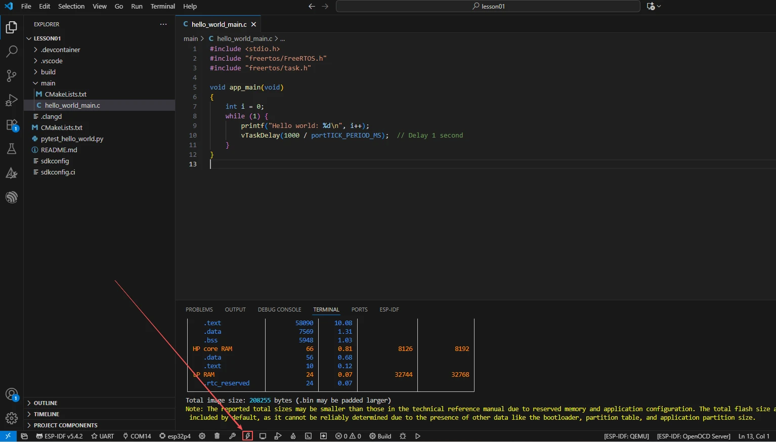
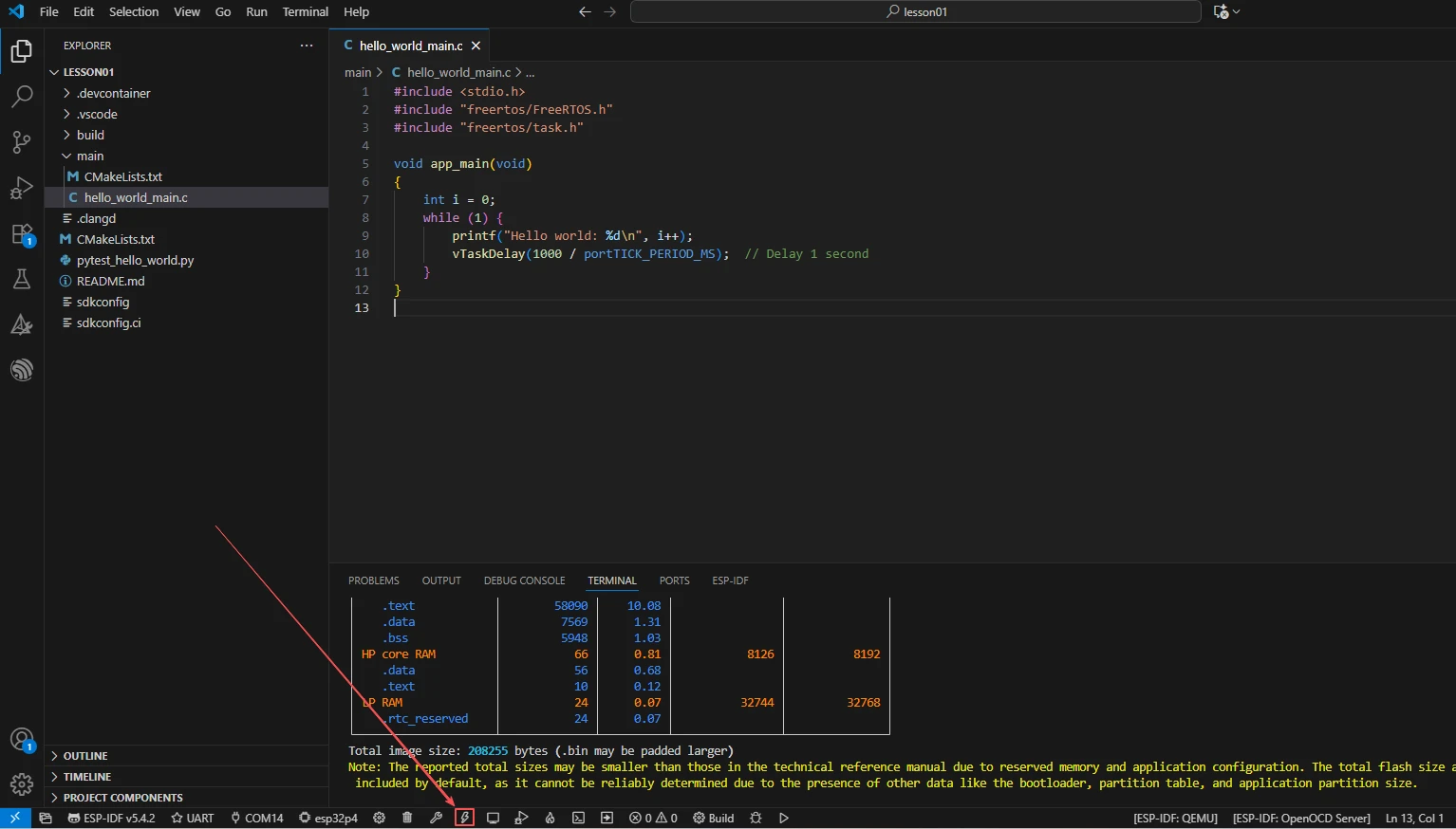
Connect the first development board, click Select Port to Use to select the corresponding serial port, then click Flash to flash the TX firmware.
Open the project again and select Lesson14_RX_SX1262_Wireless_Module (receiver). Re-apply steps 2–7 to set the ESP-IDF version, UART serial port, target chip, Flash, and SX1262 configuration, then click Full Clean followed by Build to compile the RX project.
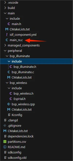
Connect the second development board, click Select Port to Use to select the corresponding serial port, then click Flash to flash the RX firmware.
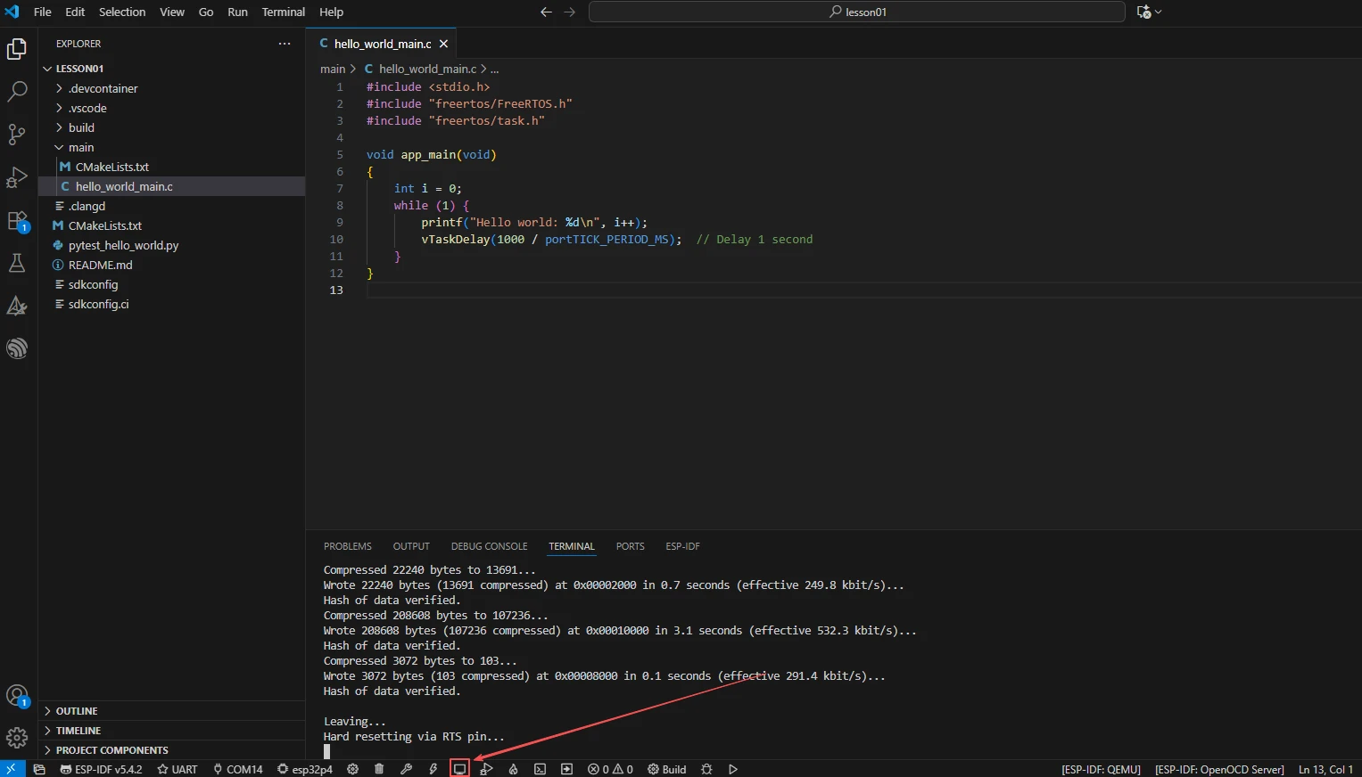
Select the serial ports corresponding to the TX and RX development boards respectively, and click Monitor to open the serial monitor. Confirm that the transmitter continuously outputs transmission logs and the receiver continuously outputs reception logs; press Ctrl + ] to exit the monitor.
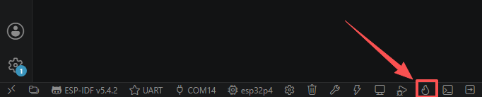
Finally, you can use the one-click operation button in the ESP-IDF status bar to sequentially perform compilation, flashing, and opening the serial monitor. Use this only after the project configuration, serial port, and code have all been confirmed correct; if you need to locate a problem, still follow the steps above one by one.
5. Hardware Operation Steps
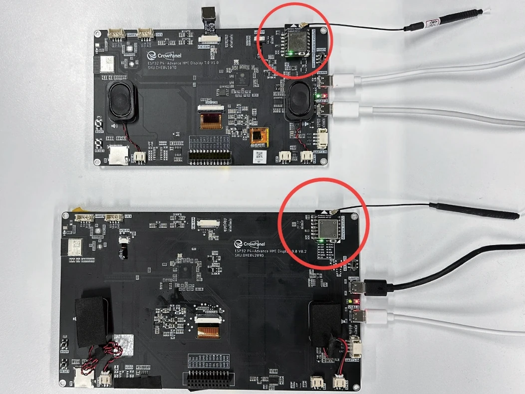
Confirm that the SX1262 module and antenna have been correctly connected on both development boards, and that the USB cable has also been connected.
Remember to supply the product with an additional power cable to ensure the development board has sufficient current and the display works properly.
After resetting the TX board, observe whether the screen displays TX_Hello World:0 and increments the count every second.
After resetting the RX board, observe whether the screen displays the LoRa RX Receiver title and the initial value RX_Hello World:0.
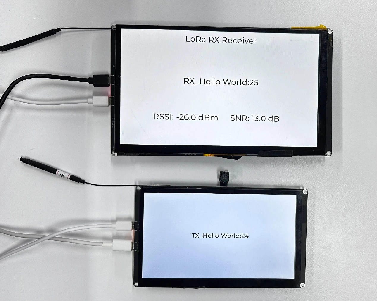
Place the two boards at a close distance (e.g., within 1 meter), and observe whether the RX board count increments with TX transmissions and whether RSSI and SNR update in real time.
Observe whether the TX board serial port prints TX msg: TX_Hello World:N to confirm it transmits once per second.
Observe whether the RX board serial port prints RX: ... (RSSI: ..., SNR: ...) to confirm successful reception.
6. Key Code Explanation
This is the SX1262 LoRa parameter configuration: frequency 915 MHz, bandwidth 125 kHz, spreading factor SF7, coding rate CR7 (4/7), private sync word, transmit power 22 dBm, preamble 8 symbols, and 1.6 V TCXO voltage. TX and RX must use identical parameters to communicate. If the frequency or spreading factor differs, the RX will be unable to receive data.
The TX side registers a transmit-complete interrupt callback. When the SX1262 finishes transmitting a frame, it triggers an IRQ, and the callback sets lora_transmittedFlag to true, prompting the main loop to send the next frame. This is a non-blocking transmission mechanism. If interrupts are not used and the blocking transmit() is used instead, the CPU will wait for transmission to complete, wasting processing time.
The receiver registers the packet-received callback and enters continuous receive mode. The IRQ callback sets lora_receivedFlag; the RX task checks that flag, reads the packet, invokes the application callback, and starts reception again. Keeping the poll interval short prevents consecutive packets from waiting too long.
if (lora_transmittedFlag) {
    lora_transmittedFlag = false;
    ...
    lora_transmissionState = bsp_sx_radio->startTransmit((uint8_t *)text, tx_len + 1);
    return true;
}
return false;
The TX task clears the completion flag before calling startTransmit, then waits for the IRQ callback before sending the next frame. This non-blocking sequence prevents overlapping transmissions and packet loss.
int state = bsp_sx_radio->readData(data, lora_received_len);
if (state == RADIOLIB_ERR_NONE) {
    ...
    rx_data_callback((const char *)data, ...);
} else if (state == RADIOLIB_ERR_CRC_MISMATCH) {
    SX1262_ERROR("CRC error!");
}
readData returns a RadioLib status; only RADIOLIB_ERR_NONE is forwarded to the UI callback. CRC mismatch is logged and discarded, preventing corrupted payloads from being displayed.
7. Experimental Results
TX board:
I (xxx) MAIN: ---------- LoRa TX ----------
I (xxx) MAIN: LCD init success
I (xxx) MAIN: The wireless module initialization was successful.
I (xxx) SX1262: transmission finished!
I (xxx) MAIN: TX msg: TX_Hello World:1
I (xxx) MAIN: TX msg: TX_Hello World:2
TX_Hello World:N, with N incrementing every second. RX board:
I (xxx) MAIN: ---------- LoRa RX ----------
I (xxx) MAIN: LoRa RX receiver started, waiting for data...
I (xxx) SX1262: Received packet!
I (xxx) SX1262: Valid Data : TX_Hello World:1
I (xxx) SX1262: RSSI:-45.23 dBm
I (xxx) SX1262: SNR:9.50 dB
I (xxx) MAIN: RX: RX_Hello World:1 (RSSI: -45.2 dBm, SNR: 9.5 dB)
RX_Hello World:N, with the count incrementing as packets are received and RSSI and SNR updating in real time. At close range, RSSI should be relatively strong (approximately −40 to −60 dBm), and SNR is typically positive (approximately 5 to 12 dB). If the RX count does not increment, check whether the LoRa parameters on both ends match and whether the antenna is properly connected; if RSSI is extremely low, move the boards closer or check the antenna connection.