Lesson15_SPI_nRF24L01: ESP32-P4 nRF24L01 Wireless Transceiver Communication
1. Course Introduction
This lesson uses ESP-IDF to drive the nRF24L01 wireless module through the SPI interface and the RadioLib library, implementing point-to-point data transmission and reception. The lesson includes two projects, TX (transmit) and RX (receive), requiring two ESP32-P4 development boards to be paired for use. The TX board sends an incrementing counter data packet NRF24_TX_Hello World:N every second and displays the count on the screen; the RX board displays the NRF24_RX_Hello World:N count on the screen after receiving.
Compared with the LoRa in Lesson14, the nRF24L01 operates in the 2.4 GHz ISM band, uses GFSK modulation, offers higher transmission rates but shorter communication distance. After flashing the program, the screens of both boards display the transmit and receive counts in real time. Through this experiment, learners will complete a full wireless communication link verification covering SPI configuration, nRF24L01 initialization, transceiver address matching, and LVGL display.
2. Learning Objectives
- Be able to open the TX and RX projects of Lesson15 in ESP-IDF and set the target chip to
esp32p4. - Be able to describe the SPI wiring of the nRF24L01 (SCK/MISO/MOSI/CS/CE/IRQ) and the function of each pin.
- Be able to explain why the TX and RX pipe addresses must be identical for communication to occur.
- Be able to complete compilation and flashing of both boards, and observe the TX count incrementing and the RX count incrementing with reception.
- Be able to determine whether address matching and the wireless link are functioning properly based on whether the RX receives data.
3. Prerequisites
- Hardware: CrowPanel Advanced 7 / 9 / 10.1-inch ESP32-P4 HMI AI Display development board × 2; two USB Type-C data cables that support data transfer; two nRF24L01 modules, with one module connected to each development board.
- Compatibility note: The hardware and software code for the 7 / 9 / 10.1-inch development boards are fully interchangeable; only the board size differs. Please select the appropriate model based on display size and usage scenario.
- Software: VS Code, ESP-IDF Extension (ESP-IDF v5.5.4 or later).
- Project dependencies: Keep
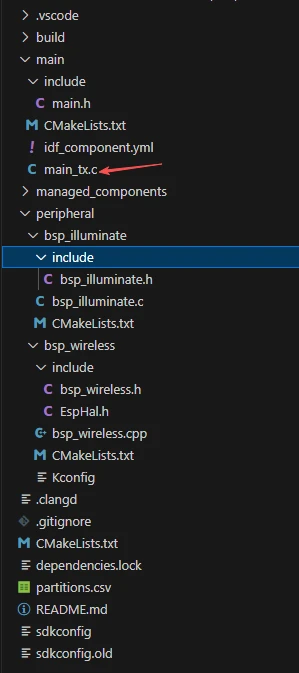
main/main_tx.cfor the TX project,main/main_rx.cfor the RX project, as well as theperipheral/bsp_wirelessandperipheral/bsp_illuminatecomponents and theRadioLibmanaged component. - Configuration: Target chip
esp32p4; SPI3, SCK=GPIO8, MISO=GPIO7, MOSI=GPIO6, CS(GPIO28)=NRF24_GPIO_CS, CE(GPIO27)=NRF24_GPIO_CE, IRQ(GPIO9)=NRF24_GPIO_IRQ.
Code download link:
4. Software Operation Steps
In VS Code, open the ESP-IDF Extension panel, click Open ESP-IDF Project, and select the Lesson15_TX_nRF2401_Wireless_RF_Module folder (transmit end).
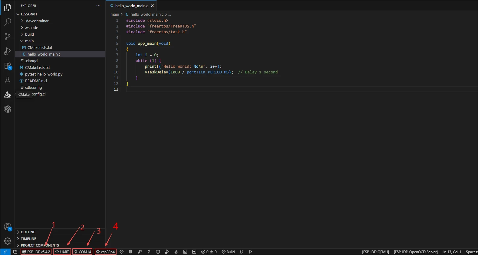
First select the code runtime environment ESP-IDF v5.5.4, set the flashing method to UART, then select the serial port corresponding to the actual development board. Subsequently, in the ESP-IDF Extension panel, click Set Espressif Device Target and select esp32p4. After the configuration is complete, the status bar should display ESP-IDF v5.5.4, UART, the required COM port, and ESP32-P4.
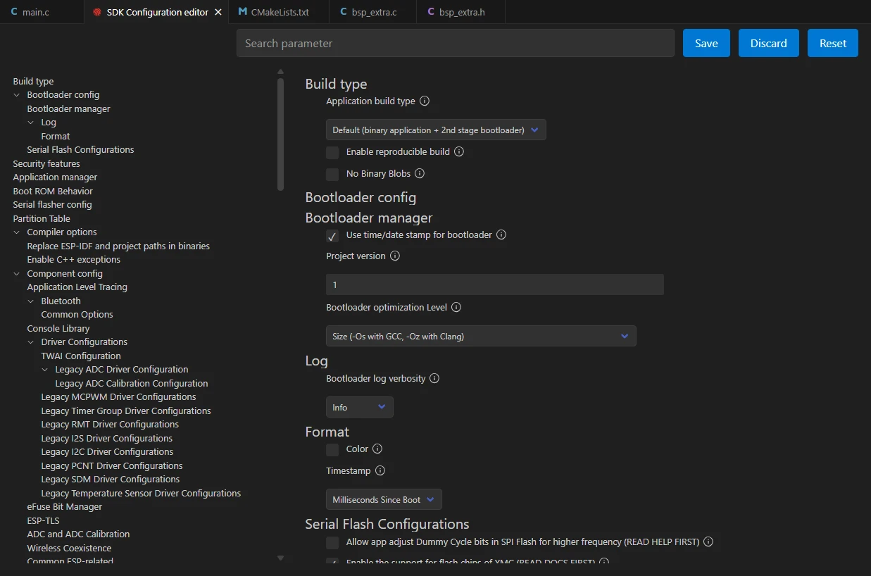
Click SDK Configuration Editor in the bottom status bar of VS Code or in the ESP-IDF extension panel, and wait until the configuration page is fully loaded before modifying parameters. If the page is still loading, do not execute Build immediately.

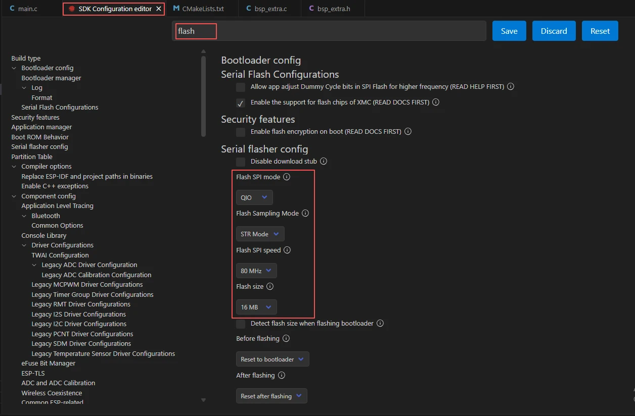
In the search box, type flash, and ensure Flash SPI mode: QIO; Flash Sampling Mode: STR Mode; Flash SPI speed: 80 MHz; Flash size: 16 MB. These parameters should match the on-board Flash of the Advance-P4.
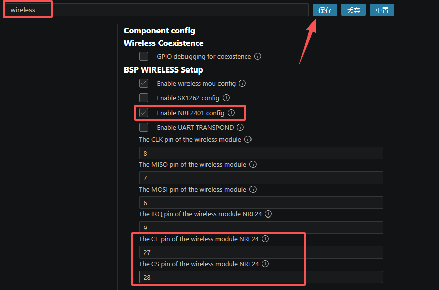
In the search box, type wireless, check only Enable NRF2401 config, and disable the wireless module configurations for SX1262, ESP32-C6, ESP32-H2, and others not used in this lesson. This setting must be completed separately for both the TX and RX projects.
Next, refer to the "4. Software Operation Steps" in
Lesson07_Turn_on_the_Screento complete the detailed SDK configuration; the relevant configuration methods were covered in Lesson 7.Note: The LVGL font size used in this lesson is 42 pt; please modify it accordingly.
After verifying the configuration is correct, click Save in the upper right corner; confirm the changes are saved, then execute Build to compile.
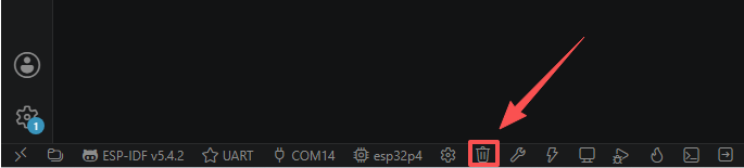
Click Full Clean to clear the cache left by the previous compilation. Perform this operation after the first compilation, after switching project configuration, or after modifying SDK parameters, to avoid old configurations affecting the new compilation results.
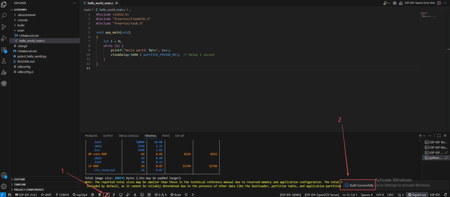
Click Build to compile the TX project. On success, the output shows Project build complete.
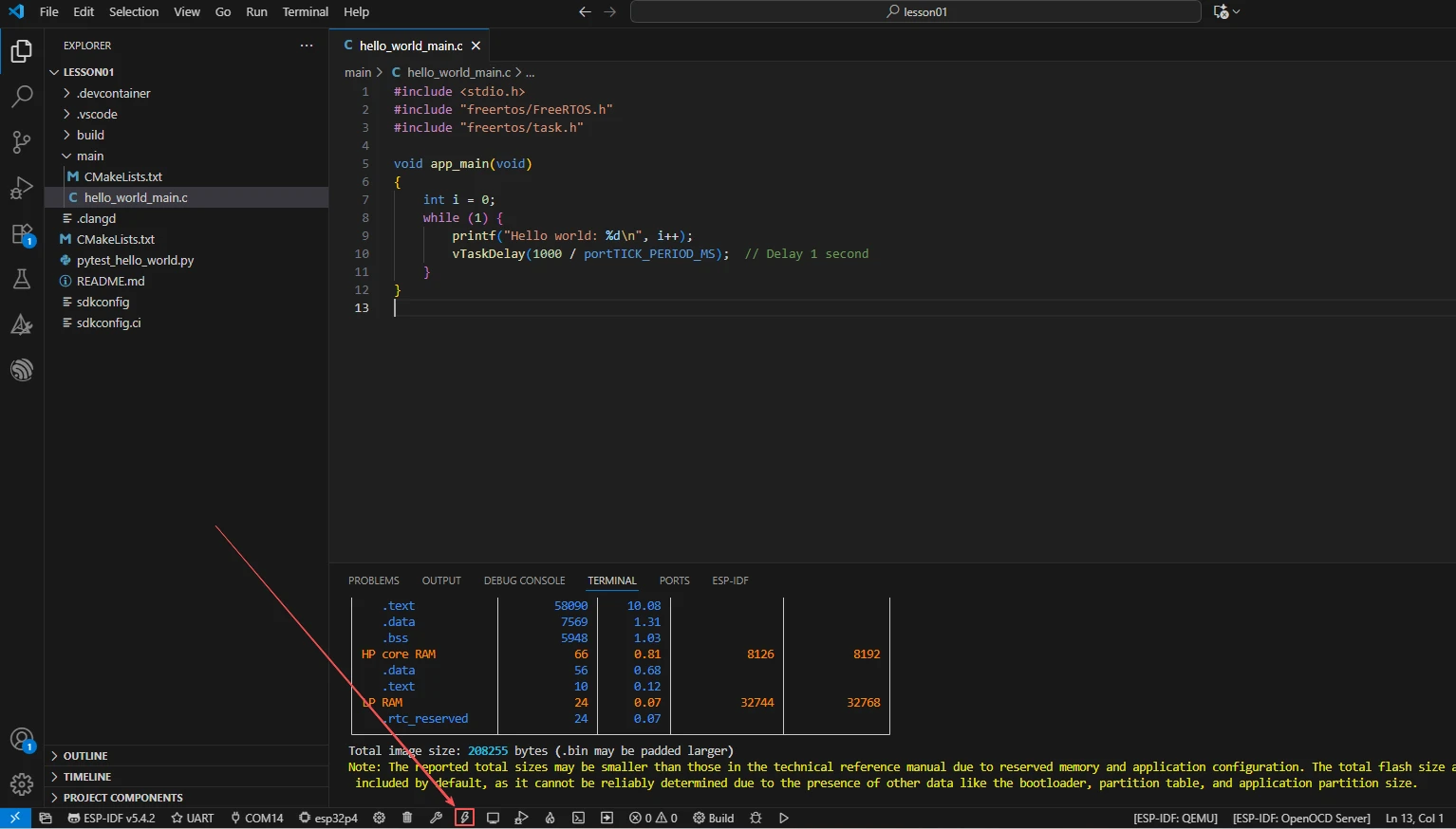
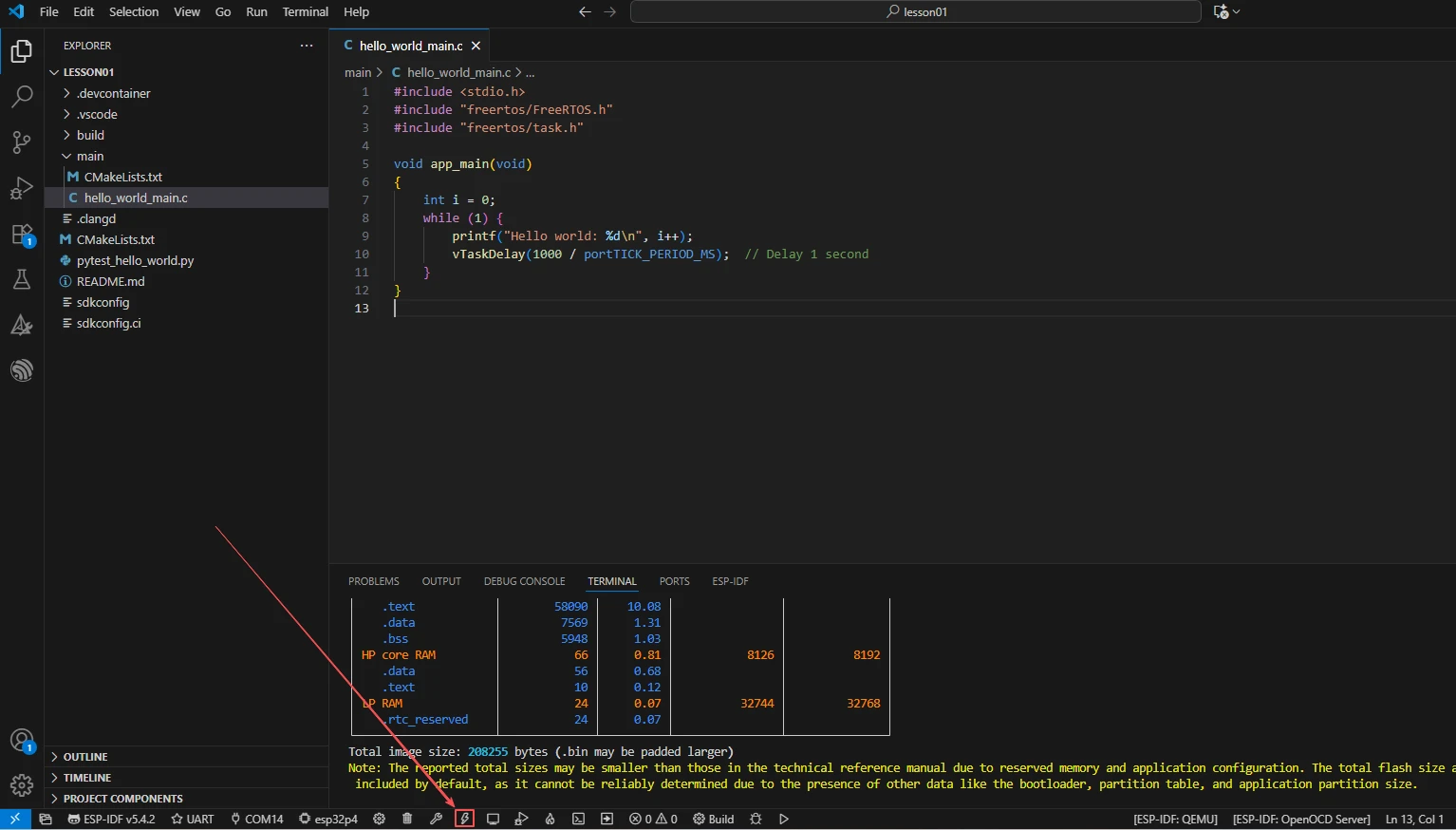
Connect the first development board, click Select Port to Use to select the corresponding serial port, then click Flash to flash the TX firmware.
Open the project again, and select Lesson15_RX_nRF2401_Wireless_RF_Module (receive end). Re-apply steps 2–7 to set the ESP-IDF version, UART serial port, target chip, Flash, and nRF24L01 configuration, then click Full Clean before clicking Build to compile the RX project.
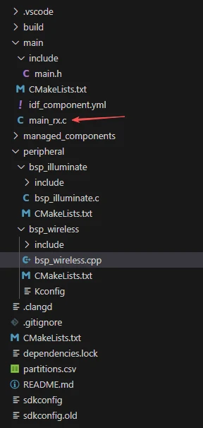
Connect the second development board, click Select Port to Use to select the corresponding serial port, then click Flash to flash the RX firmware.
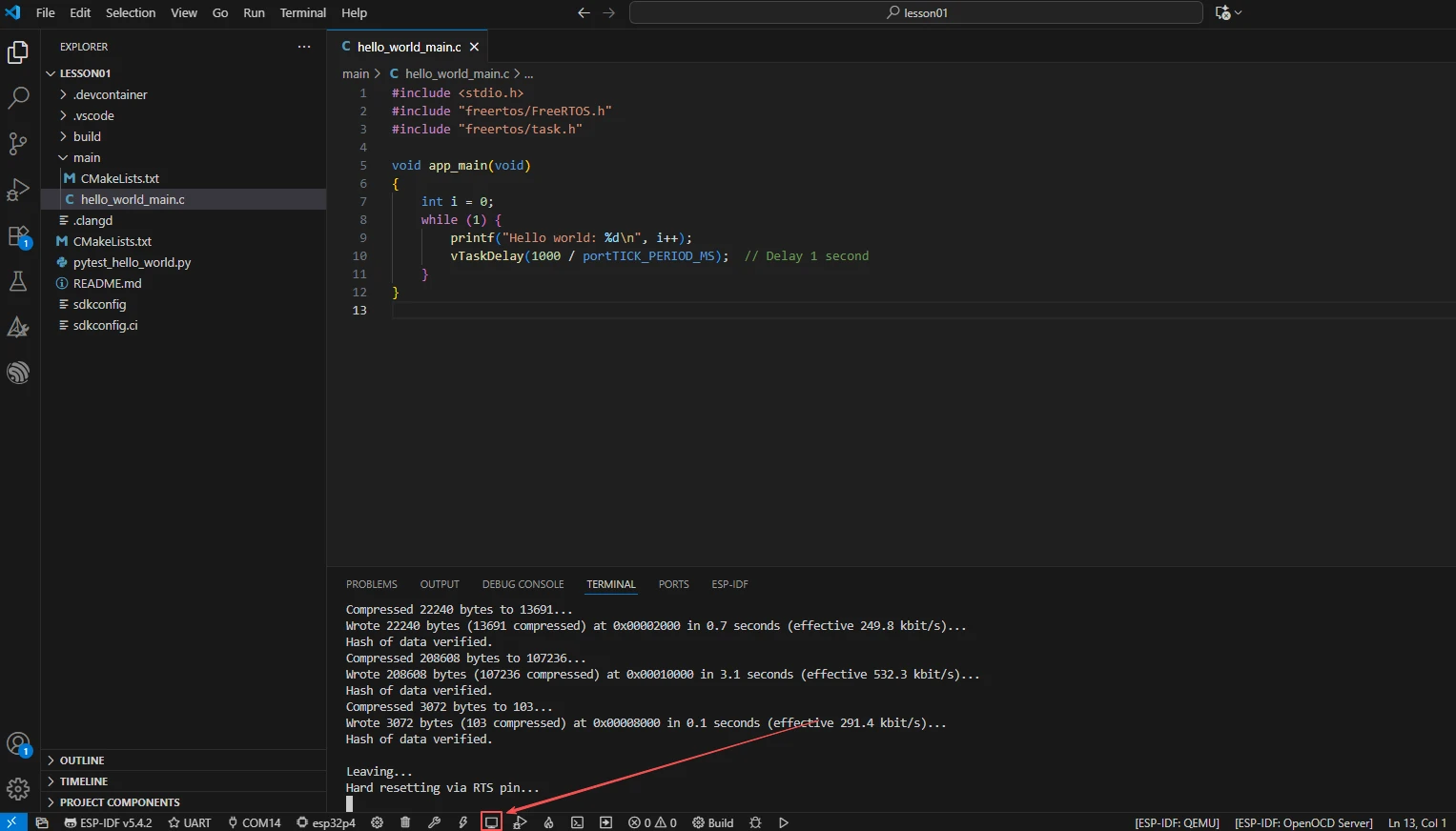
Select the serial ports corresponding to the TX and RX development boards respectively, and click Monitor to open the serial monitor. Confirm that the transmit end continuously outputs transmission logs and the receive end continuously outputs reception logs; press Ctrl + ] to exit the monitor.
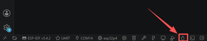
Finally, you may use the one-click operation button in the ESP-IDF status bar to sequentially execute compile, flash, and open the serial monitor. Use this only after the project configuration, serial port, and code have all been verified; if you need to locate a problem, still follow the steps above and execute them one by one.
5. Hardware Operation Steps
Confirm that the nRF24L01 modules and antennas on both development boards have been properly connected, and that the USB cables have also been connected.
Remember to provide an additional power cable for the product to ensure sufficient current for the development board and a proper display.
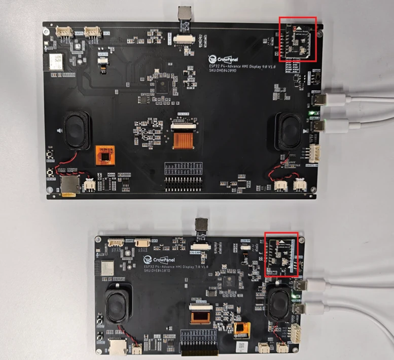
After the TX board resets, observe whether the screen displays NRF24_TX_Hello World:0 and increments the count every second.
After the RX board resets, observe whether the screen displays the nRF24L01 RX Receiver title and the initial value NRF24_RX_Hello World:0. 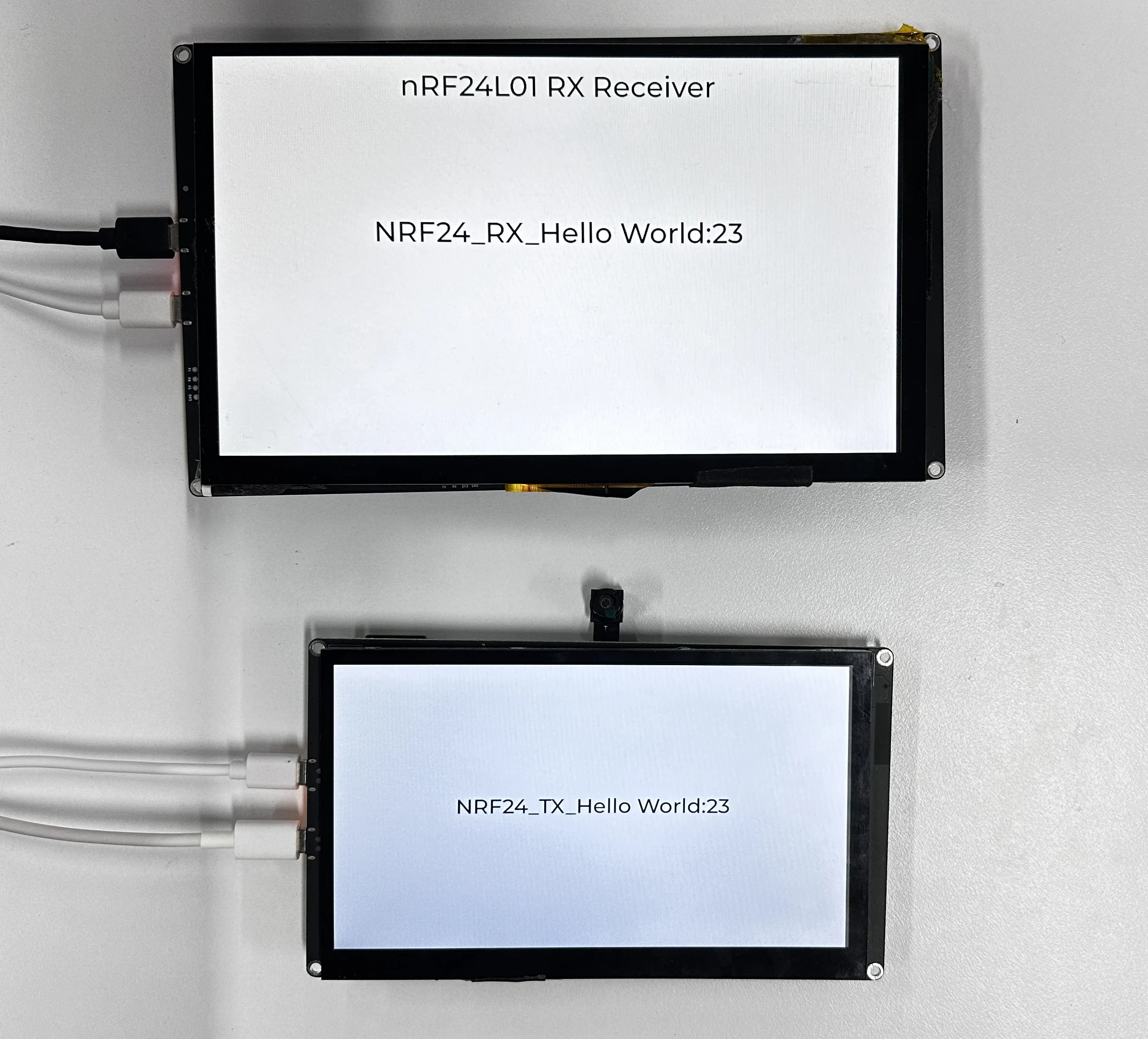
Place the two boards at a relatively close distance (e.g., within 1 meter) and observe whether the RX board count increments with TX transmission.
Observe whether the TX board serial port prints transmission finished! and Sent: ..., confirming transmission every second.
Observe whether the RX board serial port prints NRF24 RX: ..., confirming successful reception.
6. Key Code Explanation
bsp_nrf_radio->begin(2400, 250, 0, 5);
uint8_t addr[] = {0x01, 0x02, 0x11, 0x12, 0xFF};
bsp_nrf_radio->setTransmitPipe(addr);
nRF24 initialization: frequency 2400 MHz, rate 250 kbps, address width 5 bytes. The TX sets the transmit pipe address; the RX must use the same address and call setReceivePipe, otherwise it will not receive data. If the addresses do not match, the two boards will not communicate with each other, and the RX count will remain 0.
The TX increments its counter first, formats the payload inside send_nrf24_pack_radio, and sends it once per second. The nRF24L01 payload is limited to 32 bytes, so the formatted text must remain within that size.
The RX registers the receive callback and starts continuous reception. The polling task calls received_nrf24_pack_radio(32) every 10 ms; the wireless component reads up to the 32-byte maximum and invokes the registered callback when a packet arrives.
int state = bsp_nrf_radio->readData(data, len);
if (state == RADIOLIB_ERR_NONE) {
    if (nrf24_rx_data_callback != NULL) {
        nrf24_rx_data_callback((const char *)data, len);
    }
}
bsp_nrf_radio->startReceive();
After a successful read, the component calls the application callback, which updates the LVGL label and serial log. The receive path is kept active by the component's polling loop, so packets continue to be accepted.
7. Experimental Observations
TX board:
I (xxx) MAIN: ---------- nRF24L01 TX ----------
I (xxx) MAIN: LCD init success
I (xxx) MAIN: The nRF24L01 wireless module initialization was successful.
I (xxx) NRF2401: transmission finished!
I (xxx) NRF2401: Sent: NRF24_TX_Hello World:1
NRF24_TX_Hello World:N, with N incrementing every second. RX board:
I (xxx) MAIN: ---------- nRF24L01 RX ----------
I (xxx) MAIN: nRF24L01 RX receiver started, waiting for data...
I (xxx) NRF2401: Received packet!
I (xxx) NRF2401: Valid Data : NRF24_TX_Hello World:1
I (xxx) MAIN: NRF24 RX: NRF24_RX_Hello World:1
NRF24_RX_Hello World:N count, which increments with reception. Reception should be stable at close range without packet loss. If the RX count does not increment, first check whether the addresses of the two boards match and whether the CS/CE/IRQ pins are correct; if packet loss occurs occasionally, it is normal for the nRF24L01 to lose packets in an interference-prone environment.