Lesson16_WiFi_Weather: Obtaining Weather Data via ESP32-P4 WiFi Networking
1. Course Introduction
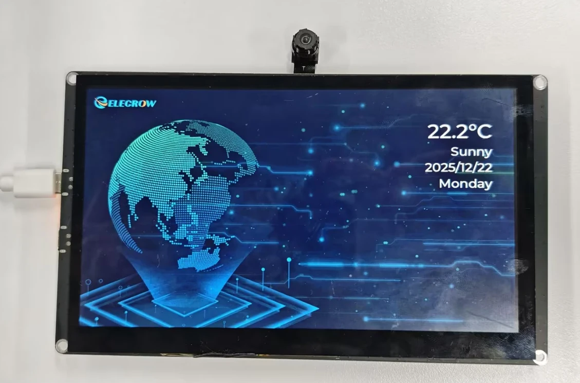
This lesson uses ESP-IDF to connect to a router via WiFi STA mode and obtain weather data (temperature, weather description, timestamp) through HTTP requests, then displays the weather information on a MIPI DSI screen by overlaying text on a full-screen background image. After the firmware is flashed, the development board powers on and resets, connects to the specified WiFi, obtains the weather data, then sets the system clock, and the screen displays the temperature, weather, date, and day of the week.
This lesson serves as the foundation for WiFi networking courses, integrating the screen display from Lesson07 with WiFi network communication. Through this experiment, learners will complete a full networking application chain validation covering WiFi STA initialization, HTTP requests, JSON parsing, system time synchronization, and LVGL resource loading.
2. Learning Objectives
- Be able to open the Lesson16 project in ESP-IDF and set the target chip to
esp32p4. - Be able to explain the WiFi STA mode initialization flow (netif, event loop, wifi init, connect).
- Be able to explain why true network connectivity is only achieved after obtaining an IP (
IP_EVENT_STA_GOT_IP). - Be able to complete compilation and flashing, and observe whether the screen displays weather, temperature, and date information.
- Be able to determine whether the networking link is functioning properly based on whether WiFi is connected and whether weather data is successfully obtained.
3. Preparation
- Hardware: One CrowPanel Advanced 7 / 9 / 10.1-inch ESP32-P4 HMI AI Display development board, and one USB Type-C data cable that supports data transfer.
- Compatibility note: The 7 / 9 / 10.1-inch development boards share the same hardware and software code, differing only in board size; please select the appropriate model based on display size and use case.
- Software: VS Code, ESP-IDF Extension (ESP-IDF v5.5.4 or later).
- Project dependencies: Retain the
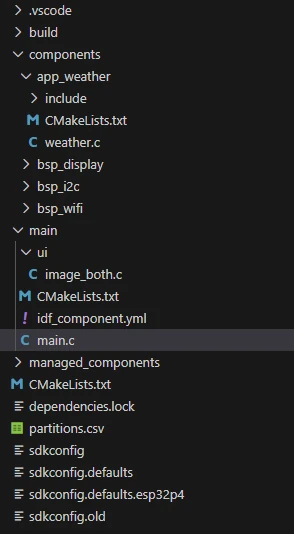
main/main.c,components/bsp_wifi,components/app_weather,components/bsp_display, andcomponents/bsp_i2ccomponents, along with thelvgl,esp_lvgl_port,esp_lcd_ek79007, andesp_lcd_touch_gt911managed components. - Network: An available 2.4 GHz WiFi router; the SSID and password must be configured in the
bsp_wifi_connectcall withinmain.c. - Resources:
main/ui/image_both.ccontains the full-screen background image data and must be retained.
Code download link:
4. Software Operation Steps
In VS Code, open the ESP-IDF Extension panel, click Open ESP-IDF Project, and select the Lesson16_Get_weather_via_WiFi folder.
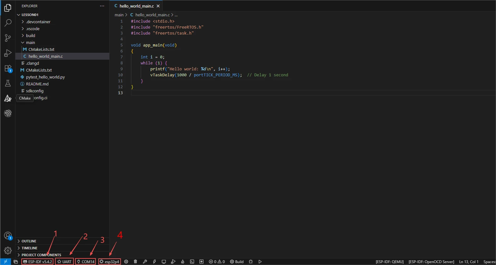
First, select the code runtime environment ESP-IDF v5.5.4, set the flashing method to UART, and then select the serial port that actually corresponds to the development board. Next, in the ESP-IDF Extension panel, click Set Espressif Device Target and select esp32p4. After the configuration is complete, the status bar should display ESP-IDF v5.5.4, UART, the required COM port, and ESP32-P4.
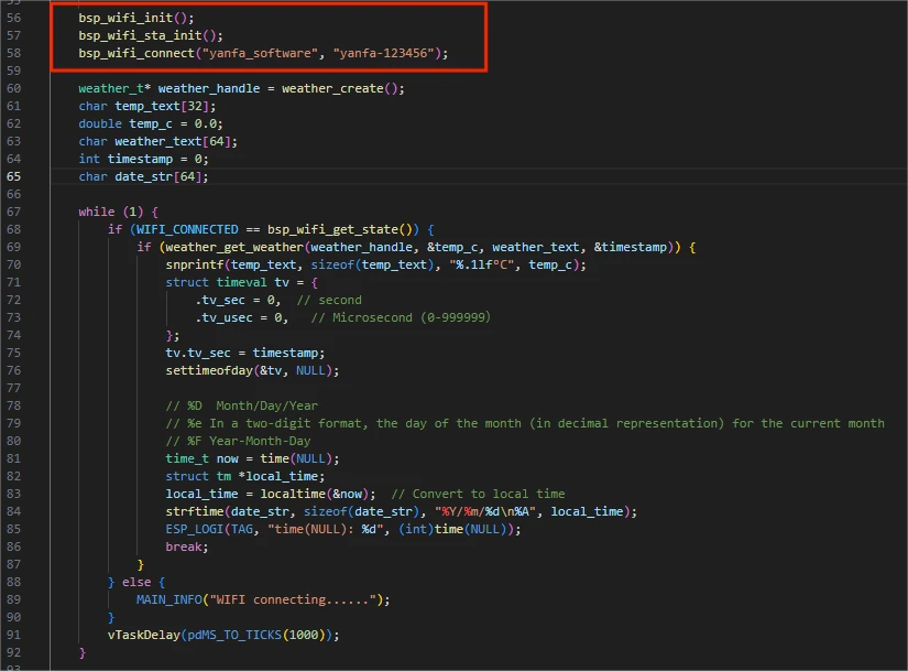
Open main/main.c and change the SSID and password in bsp_wifi_connect("yanfa_software", "yanfa-123456") to your router's information, then save.
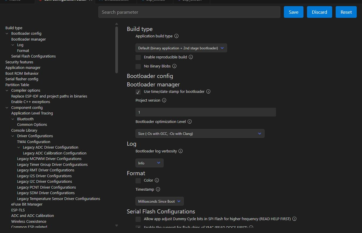
Click SDK Configuration Editor and wait for the configuration page to fully load.

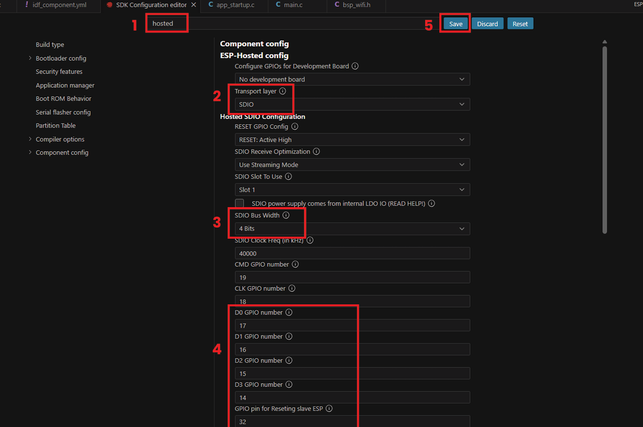
In the search box, enter hosted and set the SDIO parameters for the onboard ESP32-C6 as follows: Bus Width 4 Bits, Clock 40000 kHz, CMD GPIO 19, CLK GPIO 18, D0/D1/D2/D3 GPIO 17, 16, 15, and 14 respectively, and Reset GPIO 32.
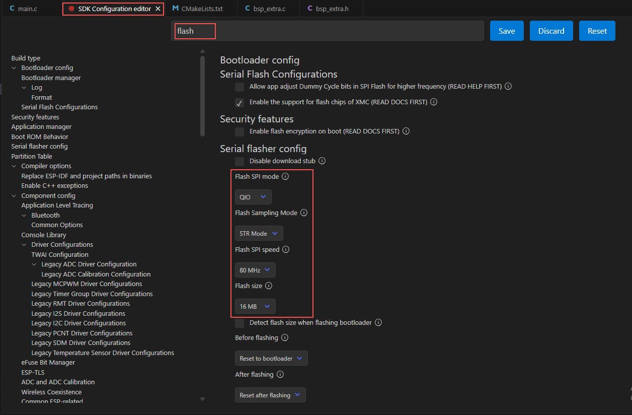
In the search box, enter flash and ensure Flash SPI mode: QIO; Flash Sampling Mode: STR Mode; Flash SPI speed: 80 MHz; Flash size: 16 MB.
Then refer to "4. Software Operation Steps" in
Lesson07_Turn_on_the_Screento complete the detailed SDK configuration; the relevant configuration methods were covered in Lesson 7.Note: This lesson uses LVGL font sizes 30 and 48; please modify accordingly.
After verifying the configuration is correct, click Save in the top-right corner; confirm the changes have been saved, then run Build to compile.
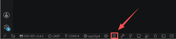
Click Full Clean to clear the cache left over from the previous compilation. Running this after the first compilation, after switching project configurations, or after modifying SDK parameters prevents old configurations from affecting the new build result.
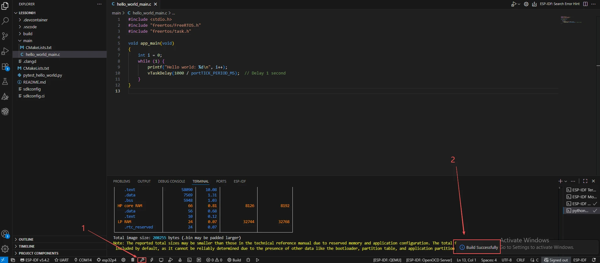
Click Build to compile the project. On success, the output will read Project build complete.
Confirm that the development board is connected to the computer via USB, click Select Port to Use to choose the serial port, then click Flash to flash the firmware.
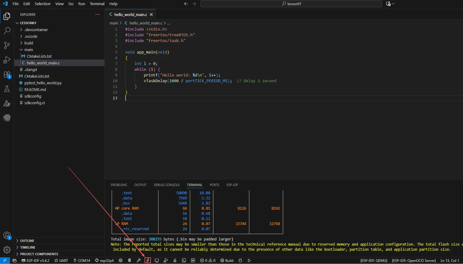
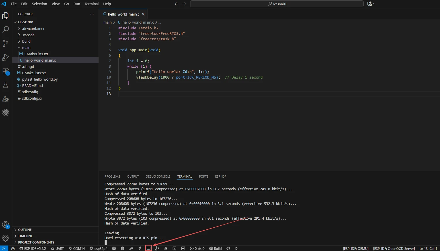
After flashing is complete, click Monitor to open the serial monitor; you should see WiFi connection and weather fetching logs. Press Ctrl + ] to exit the monitor.
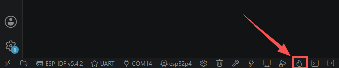
Finally, you can use the one-click operation button in the ESP-IDF status bar to sequentially run compilation, flashing, and opening the serial monitor. Use this only after the project configuration, serial port, and code have all been verified; if you need to pinpoint a problem, you should still follow the steps above one by one.
5. Hardware Operation Steps
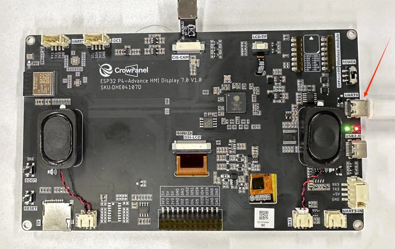
Connect the ESP32-P4 development board to the computer using a USB data cable. Confirm that the WiFi antenna (if required) and the LCD ribbon cable are connected.
After flashing is complete and the board resets, observe whether the serial port prints WiFi connected with IP:... to confirm successful network connection.
Observe whether the serial port prints weather data (temperature, weather description, timestamp) to confirm the HTTP request succeeded.
Observe whether the screen displays the background image overlaid with temperature, weather, date, and day-of-week text, with the backlight turned on.
6. Key Code Explanation
Three-step WiFi initialization: bsp_wifi_init initializes NVS, netif, the event loop, and the WiFi driver; bsp_wifi_sta_init creates the STA network interface, registers the event callback, sets STA mode, and starts it; bsp_wifi_connect configures the SSID/password and connects. If the SSID or password is incorrect, the device will repeatedly fail to reconnect.
if (WIFI_CONNECTED == bsp_wifi_get_state()) {
if (weather_get_weather(weather_handle, &temp_c, weather_text, ×tamp)) {
...
}
}
An HTTP request is sent only after WIFI_CONNECTED (i.e., an IP has been obtained). If a request is made before an IP is assigned, DNS resolution or the connection will fail. weather_get_weather internally performs the HTTP GET and JSON parsing, and returns the temperature, description, and Unix timestamp.
The weather API returns a Unix timestamp. The current code initializes the timeval, assigns the timestamp to tv_sec, and then calls settimeofday; subsequent time()/localtime() calls therefore produce the correct date and weekday. Without this step, the displayed date falls back to the epoch.
LV_IMAGE_DECLARE(image_both);
ui_home = lv_image_create(lv_screen_active());
lv_image_set_src(ui_home, &image_both);
lv_obj_set_size(ui_home, H_size, V_size);
image_both is compiled from main/ui/image_both.c. The updated LVGL 9 API uses lv_image_create, lv_image_set_src, and lv_screen_active; the object is explicitly sized to the full display before the text labels are placed on top.
temperature_label_ = lv_label_create(ui_home);
lv_obj_set_style_text_font(temperature_label_, &lv_font_montserrat_48, 0);
lv_obj_set_style_text_color(temperature_label_, lv_color_hex(0xFFFFFF), 0);
The temperature label is created on top of the background image, using Montserrat 48 white font; other labels (weather, date, day of the week) use Montserrat 30. The fonts must be enabled in the LVGL configuration; otherwise, the text will not be displayed.
7. Experimental Results
After the program is flashed and the board resets, the serial monitor outputs:
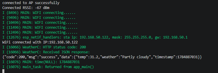
Screen behavior: the backlight turns on and displays a full-screen background image, with the top-right corner showing, in order, the temperature (e.g., 28.5 C), weather description (e.g., Partly Cloudy), date (e.g., 2026/07/22), and day of the week (e.g., Wednesday), all in white text. If WiFi cannot connect, check the SSID/password and signal strength; if weather fetching fails, check whether the network can reach the weather API server; if the screen shows no text, check whether the fonts are enabled and whether the background image is retained.