Lesson17_WiFi_Functions: ESP32-P4 WiFi Three Operating Modes
1. Course Introduction
This lesson uses ESP-IDF to demonstrate the three WiFi operating modes of the ESP32-P4 via the WiFi driver: Station (STA), softAP (AP), and AP+STA (hybrid mode with NAPT forwarding). The course includes three independent projects; learners can compile and flash each one separately to experience every mode. In Station mode, the development board acts as a client connecting to a router; in softAP mode, the development board acts as a hotspot for other devices to connect; in AP+STA mode, the development board simultaneously acts as both a client and a hotspot, and uses NAPT to allow AP clients to access the internet through the STA.
After the program is flashed, the serial monitor outputs the WiFi event log corresponding to the mode (connection success, IP acquisition, station joining or leaving, etc.). Through this experiment, learners will complete the full-link verification of initialization, event handling, and network interface management for the three WiFi modes: STA, AP, and AP+STA.
2. Learning Objectives
- Be able to open the three Lesson17 projects in ESP-IDF and set the target chip to
esp32p4. - Be able to explain the differences and applicable scenarios among the three modes: STA, AP, and AP+STA.
- Be able to explain the workflow of the WiFi event-driven mechanism (WIFI_EVENT/IP_EVENT).
- Be able to complete the compilation and flashing of all three modes, and observe the serial log to confirm each mode works properly.
- Be able to connect a phone to the AP in AP+STA mode and access the internet through the development board.
3. Prerequisites
- Hardware: CrowPanel Advanced 7 / 9 / 10.1 inch ESP32-P4 HMI AI Display development board (one); a USB Type-C data cable that supports data transfer (one); a phone or computer for connecting to the AP for testing.
- Compatibility note: The hardware and software code for the 7 / 9 / 10.1 inch development boards are fully interchangeable; only the board size differs. Please select the appropriate model based on display size and usage scenario.
- Software: VS Code, ESP-IDF Extension (ESP-IDF v5.5.4 or above).
- Project dependencies: The three projects are
ESP32_P4-station,ESP32_P4-softAP, andESP32_P4-softap_sta, all depending on system components such asesp_wifiandnvs_flash. - Network: An available 2.4 GHz WiFi router (required for STA and AP+STA modes); the SSID and password need to be configured in the source code macro definitions.
Code download link:
4. Software Operation Steps
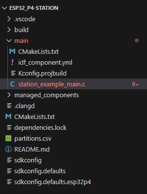
In VS Code, open the ESP-IDF Extension panel, click Open ESP-IDF Project, and select the ESP32_P4-station folder (Station mode).
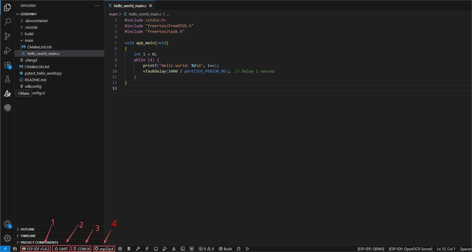
First select the code runtime environment ESP-IDF v5.5.4, set the flashing method to UART, and then select the serial port that actually corresponds to the development board. Then click Set Espressif Device Target in the ESP-IDF Extension panel and select esp32p4. After the setup is complete, the status bar should display ESP-IDF v5.5.4, UART, the required COM port, and ESP32-P4.
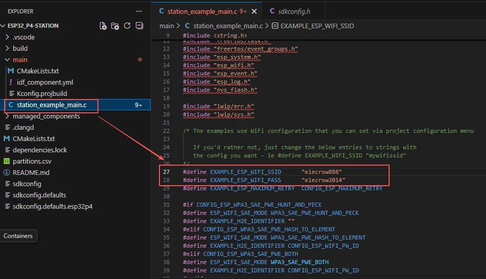
If you need to modify the Station network information, modify EXAMPLE_ESP_WIFI_SSID and EXAMPLE_ESP_WIFI_PASS in main/station_example_main.c.
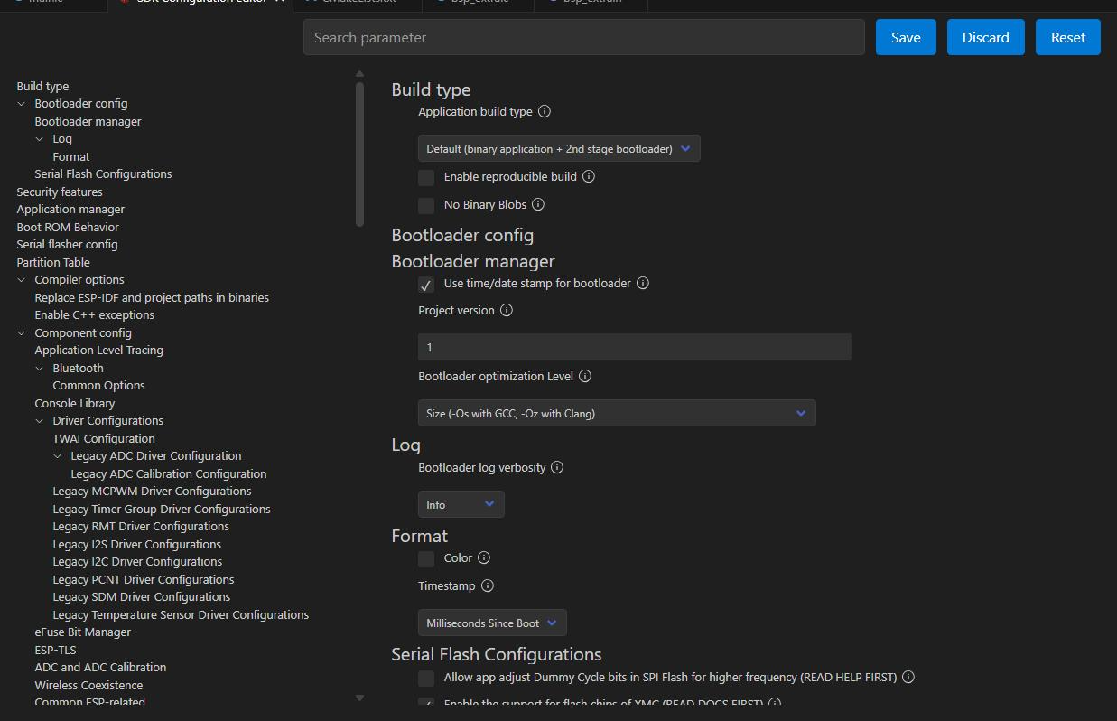
In the three projects—Station, softAP, and softap_sta—open the SDK Configuration Editor respectively and wait for the configuration page to fully load.

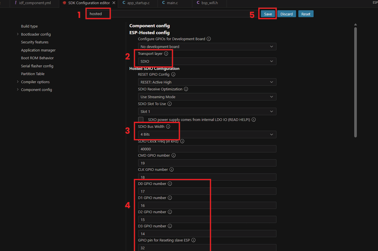
In the search box, enter hosted and set the SDIO parameters of the onboard ESP32-C6 as follows: Bus Width 4 Bits, Clock 40000 kHz, CMD GPIO 19, CLK GPIO 18, D0/D1/D2/D3 GPIO 17, 16, 15, 14 respectively, and Reset GPIO 32.
This configuration should be verified in all three projects.
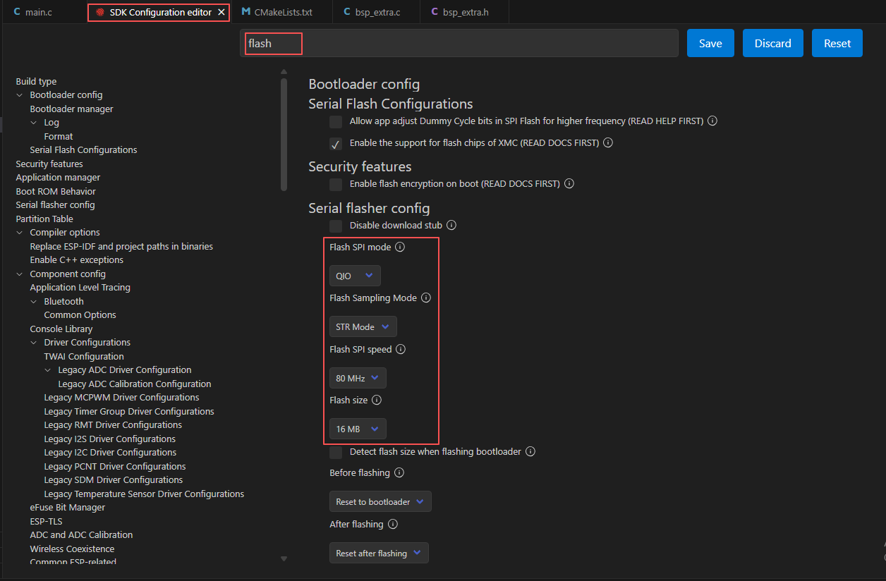
Search for flash and ensure Flash SPI mode: QIO; Flash Sampling Mode: STR Mode; Flash SPI speed: 80 MHz; Flash size: 16 MB.
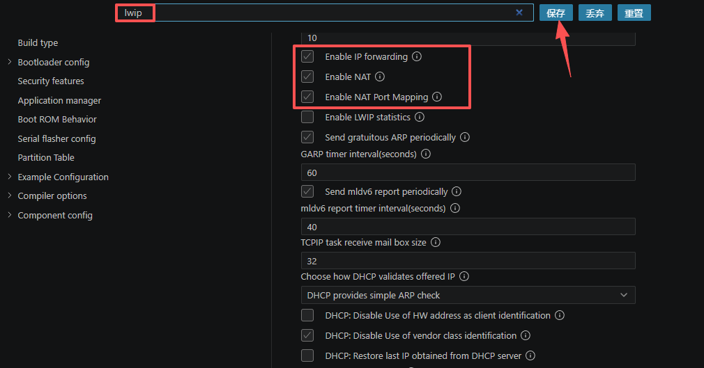
In the LWIP configuration of the AP+STA (softap_sta) project, enable Enable IP forwarding, Enable NAT, and Enable NAT Port Mapping, so that hotspot clients can forward network traffic through the Station side.
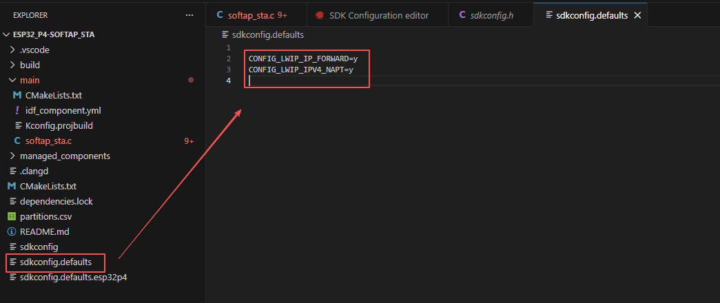
At the same time, confirm that sdkconfig.defaults contains CONFIG_LWIP_IP_FORWARD=y and CONFIG_LWIP_IPV4_NAPT=y, so that forwarding and NAPT are still retained when the configuration is regenerated.
Then refer to "4. Software Operation Steps" in
Lesson07_Turn_on_the_Screento complete the detailed SDK configuration; the relevant configuration methods have been explained in Lesson 7.
After confirming the configuration is correct, click Save in the upper right corner; verify the modifications have been saved, then execute Build to compile.
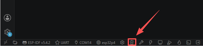
Click Full Clean to clear the cache left by the previous compilation. Perform this operation after the first compilation, after switching project configurations, or after modifying SDK parameters, so that stale configurations do not affect the new compilation result.
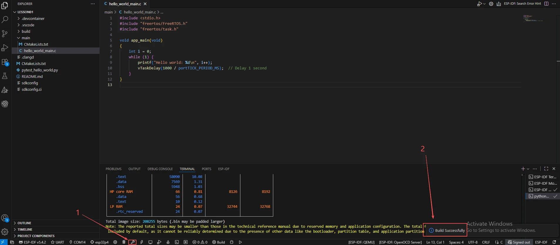
Click Build to compile the project. On success, the output Project build complete is displayed.
After connecting the development board, click Select Port to Use to choose the corresponding serial port, then click Flash to flash the firmware. After flashing, click Monitor to observe the connection log. Press Ctrl + ] to exit the monitor.
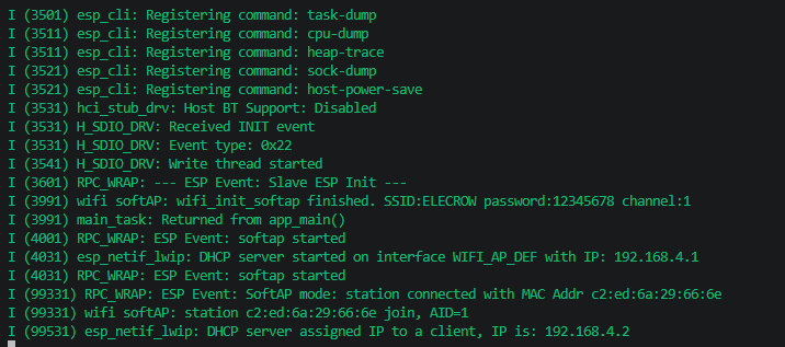
Open the ESP32_P4-softAP project (AP mode), follow steps 2–10 to confirm the target chip, WiFi parameters, Hosted, and Flash configurations, and execute Full Clean, Build, Flash, and Monitor in sequence.
After flashing is complete, the serial port should indicate that AP mode is ready; once a phone or computer connects to the ELECROW hotspot, the serial port will print the client join event and its IP information. This mode only provides a local hotspot and is not connected to an upstream network, so clients cannot access the internet by default.
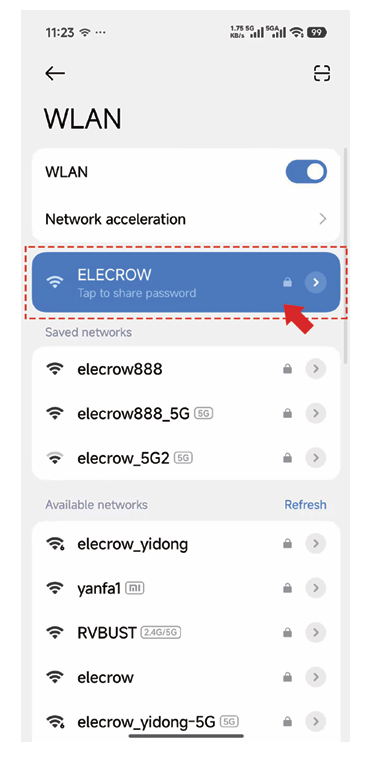
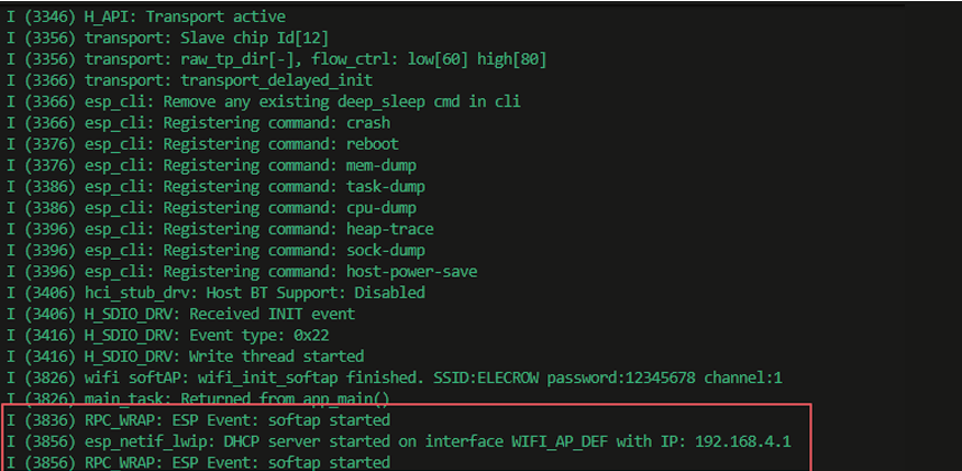
Open the ESP32_P4-softap_sta project (AP+STA mode), follow steps 2–8 to confirm the target chip, WiFi parameters, Hosted, Flash, and NAPT configurations, and execute Full Clean, Build, Flash, and Monitor in sequence.
After flashing is complete, the serial port should first show that STA has connected to the upstream WiFi, then show that AP has started; once a phone or computer connects to the ELECROW hotspot, the serial port will print the client IP and it can access the internet through NAPT.
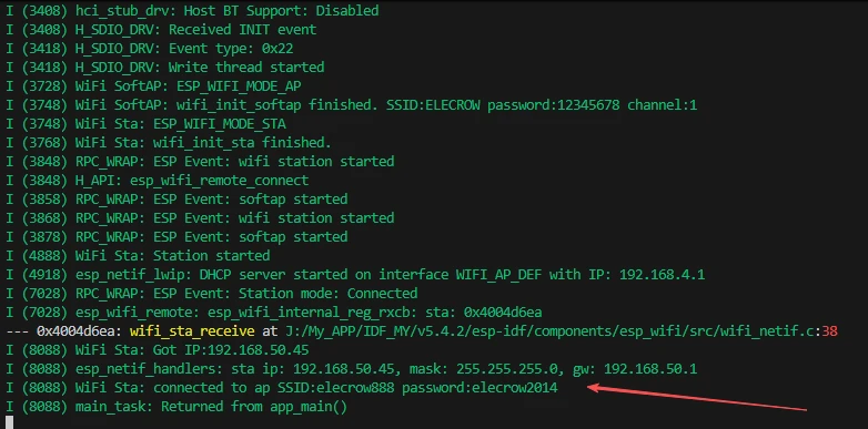
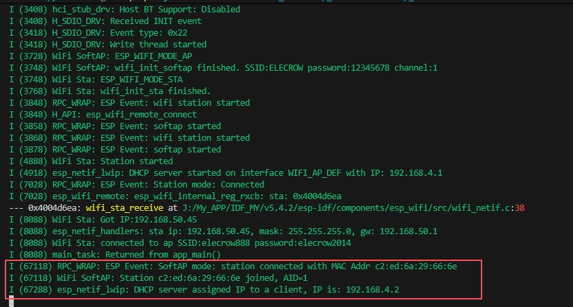
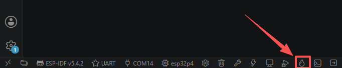
Finally, you can use the one-click operation button in the ESP-IDF status bar to sequentially execute compilation, flashing, and opening the serial monitor. Use this only after the project configuration, serial port, and code have all been confirmed correct; if you need to locate a problem, still follow the steps above and execute them one by one.
5. Hardware Operation Steps
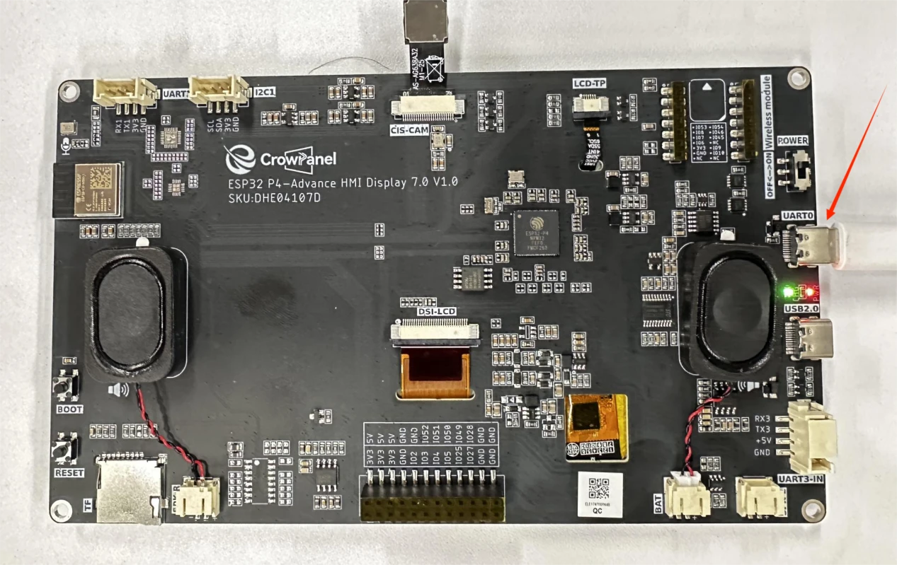
Use a USB data cable to connect the ESP32-P4 development board to the computer.
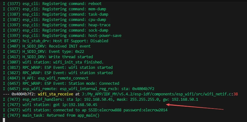
After flashing in Station mode, observe whether the serial port prints got ip:192.168.x.x to confirm it has connected to the router and obtained an IP.
After flashing in softAP mode, use a phone to search for the WiFi hotspot ELECROW, enter the password 12345678 to connect, and the serial port should print station join.
After flashing in AP+STA mode, the STA connects to the router and obtains an IP, while the AP hotspot becomes available; after the phone connects to the AP, it should be able to access the internet (NAPT forwarding), and the serial port will print both AP and STA logs.

6. Key Code Explanation
Station Mode
esp_netif_create_default_wifi_sta();
ESP_ERROR_CHECK(esp_wifi_set_mode(WIFI_MODE_STA));
ESP_ERROR_CHECK(esp_wifi_set_config(WIFI_IF_STA, &wifi_config));
ESP_ERROR_CHECK(esp_wifi_start());
STA initialization creates the default interface, loads the SSID/password plus the Kconfig-selected WPA3 SAE and authentication threshold fields, sets WIFI_MODE_STA, and starts the driver. The registered event handler calls esp_wifi_connect() on WIFI_EVENT_STA_START, retries on disconnect, sets WIFI_CONNECTED_BIT after IP_EVENT_STA_GOT_IP, and sets WIFI_FAIL_BIT after the configured retry limit.
EventBits_t bits = xEventGroupWaitBits(s_wifi_event_group,
        WIFI_CONNECTED_BIT | WIFI_FAIL_BIT, pdFALSE, pdFALSE, portMAX_DELAY);
This blocks while waiting for the connection result. The IP_EVENT_STA_GOT_IP event sets WIFI_CONNECTED_BIT, and if retries exceed the limit, WIFI_FAIL_BIT is set. portMAX_DELAY means waiting indefinitely until a result is received. This is a typical event-driven implementation.
softAP Mode
esp_netif_create_default_wifi_ap();
ESP_ERROR_CHECK(esp_wifi_set_mode(WIFI_MODE_AP));
wifi_config_t wifi_config = { .ap = { .ssid = "ELECROW", .password = "12345678", .max_connection = 4, ... } };
ESP_ERROR_CHECK(esp_wifi_set_config(WIFI_IF_AP, &wifi_config));
ESP_ERROR_CHECK(esp_wifi_start());
AP mode initialization creates the default AP interface, fills the AP SSID/password/channel/max-connection fields, applies WIFI_MODE_AP, and starts the driver. The AP event callback reports station join/leave events. An empty password requires WIFI_AUTH_OPEN; otherwise the configured WPA/WPA2 mode is used.
AP+STA Mode (with NAPT)
ESP_ERROR_CHECK(esp_wifi_set_mode(WIFI_MODE_APSTA));
esp_netif_t *esp_netif_ap = wifi_init_softap();
esp_netif_t *esp_netif_sta = wifi_init_sta();
ESP_ERROR_CHECK(esp_wifi_start());
AP+STA mode runs both AP and STA simultaneously: STA connects to the upstream router and obtains an IP, AP provides a hotspot for downstream devices, and the two network interfaces coexist.
esp_netif_set_dns_info(esp_netif_ap, ESP_NETIF_DNS_MAIN,
                       &dns_info);
esp_netif_set_default_netif(esp_netif_sta);
esp_netif_napt_enable(esp_netif_ap);
The AP+STA example routes AP clients through the STA interface. DNS information is applied to the AP netif, STA is selected as the default egress, and NAPT is enabled on the AP. Without NAPT, downstream clients can associate with the hotspot but cannot reach the upstream network.
7. Experimental Observations
Station Mode:
I (xxx) wifi station: ESP_WIFI_MODE_STA
I (xxx) wifi station: wifi_init_sta finished.
I (xxx) wifi station: retry to connect to the AP     (may retry)
I (xxx) wifi station: got ip:192.168.1.100
I (xxx) wifi station: connected to ap SSID:elecrow888 password:elecrow2014
softAP Mode:
I (xxx) wifi softAP: ESP_WIFI_MODE_AP
I (xxx) wifi softAP: wifi_init_softap finished. SSID:ELECROW password:12345678 channel:1
I (xxx) wifi softAP: station xx:xx:xx:xx:xx:xx join, AID=1   (phone connects)
AP+STA Mode:
I (xxx) WiFi SoftAP: ESP_WIFI_MODE_AP
I (xxx) WiFi Sta: ESP_WIFI_MODE_STA
I (xxx) WiFi Sta: Station started
I (xxx) WiFi Sta: Got IP:192.168.1.101
I (xxx) WiFi SoftAP: station xx:xx:xx:xx:xx:xx joined, AID=1
ELECROW hotspot, it should be able to access the internet (NAPT takes effect). If STA cannot connect to the router, check the SSID/password and signal; if AP clients cannot access the internet, confirm whether NAPT was successfully enabled; if the phone cannot find the hotspot, check the AP's SSID and channel configuration.