P4_Micropython_01_LVGL_Control_LED: Controlling LED On/Off via the LVGL Interface
1. Course Introduction
This lesson uses the CrowPanel Advanced 7-inch ESP32-P4 HMI, Elecrow's custom MicroPython firmware, LVGL 9.1, SquareLine Studio, and the Thonny IDE to build a touch-enabled temperature and humidity interface. DHT20 data is displayed on the LCD; when the ON or OFF icon is touched, the program sets GPIO48 to 1 or 0 respectively, thereby controlling the onboard LED to turn on or off. The lesson covers the complete workflow of UI creation, firmware flashing, file upload, run verification, and troubleshooting.
2. Learning Objectives
-
Be able to create a 1024 × 600 MicroPython UI with LVGL 9.1 in SquareLine Studio and correctly export
ui_images.py. -
Be able to use Thonny to flash the designated firmware to the ESP32-P4 and upload the main program, touch driver, sensor driver, and UI assets to the device.
-
Be able to explain the relationship among LVGL display refresh, GT911 touch callback, periodic DHT20 reading, and GPIO48 LED control.
-
Be able to determine whether the experiment was successful by observing the on-screen display, touch response, LED status, and console logs.
3. Preparation
-
Hardware: One CrowPanel Advanced 7 / 9 / 10.1inch ESP32-P4 HMI AI Display development board, and one USB Type-C data cable that supports data transmission.
-
Compatibility note: The hardware and software code for the 7 / 9 / 10.1-inch development boards are all interchangeable; only the board dimensions differ. Please select the appropriate model based on the display size and use case.
-
One USB data cable that supports data transmission; do not use a cable that only charges.
-
A Windows computer with the Thonny IDE installed; if the latest version fails to flash or run properly, use the validated Thonny 4.1.7 referenced in this document.
-
Elecrow's custom MicroPython firmware
lvgl_micropy_ESP32_GENERIC_P4-C6_WIFI-16_ELECROW_INCH7-9-10_1_V1_0.bin. -
Before flashing, confirm that the serial port is not occupied by other software; power off before wiring or plugging/unplugging any expansion hardware.
-
SquareLine Studio; the project must use the LVGL 9.1 and MicroPython template.
-
inch7-9-10_1_test.py,my_gt911.py,dht20.py,ui_images.py, and the firmware file from this lesson's code directory. -
Optional: DHT20 sensor. The main program will initialize the DHT20; if it is not connected correctly, the program may fail to enter the main loop.
4. Function and Asset Creation Process
Click the link below to learn how to install SquareLine Studio software and how to export the UI files you need.
https://www.elecrow.com/wiki/Get_Started_with_SquareLine_Studio.html
After gaining a basic understanding of SquareLine Studio, let's learn how to create the interface we'll need for this lesson and how to export the UI file.
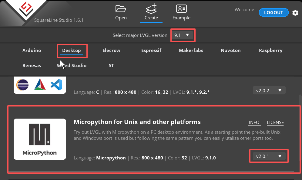
Open SquareLine Studio, select LVGL 9.1, and choose a project template that supports MicroPython. The version must match the LVGL version bundled in the firmware.
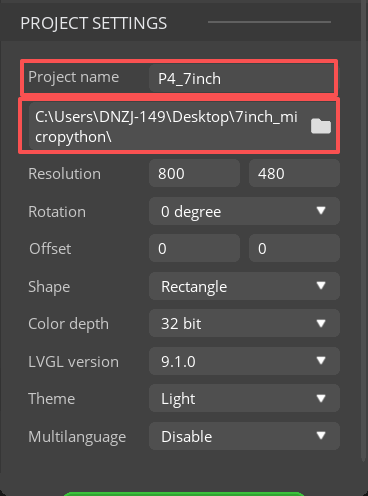
Enter the project name and save path, leave the remaining parameters at their default values from the source document, then click CREATE.
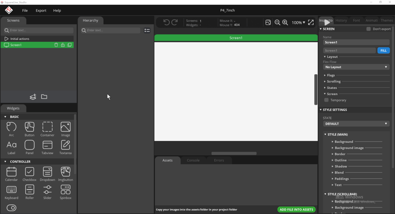
Enter the blank canvas; the canvas orientation should match the development board.
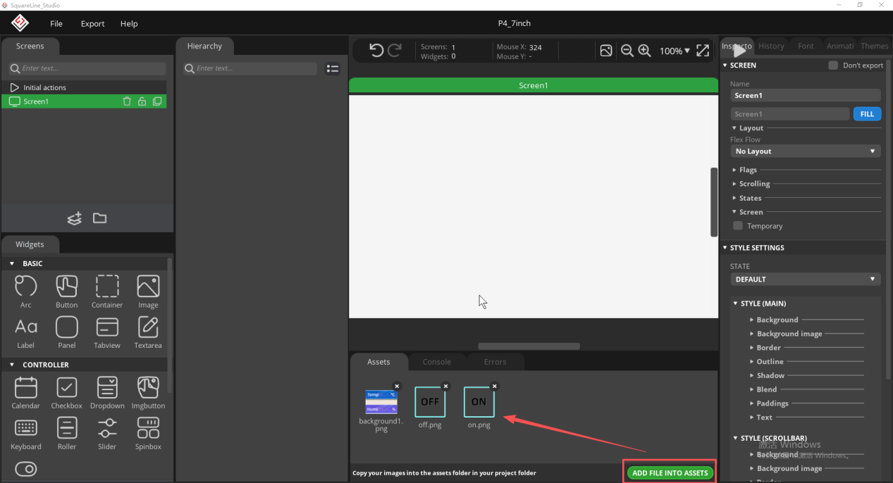
In the Assets area, click ADD FILE INTO ASSETS to import the course materials;
Materials link: https://www.elecrow.com/download/product/CrowPanel/ESP32-HMI/5.0-DIS07050H/MicroPython/assets.zip
Drag the background material onto the canvas and position it on the left side of the interface.
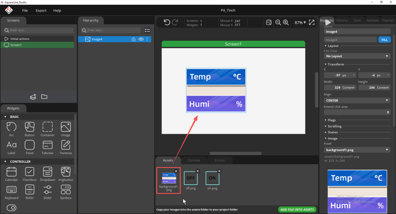
Add the first Label from the Widgets area, used to display the temperature value.
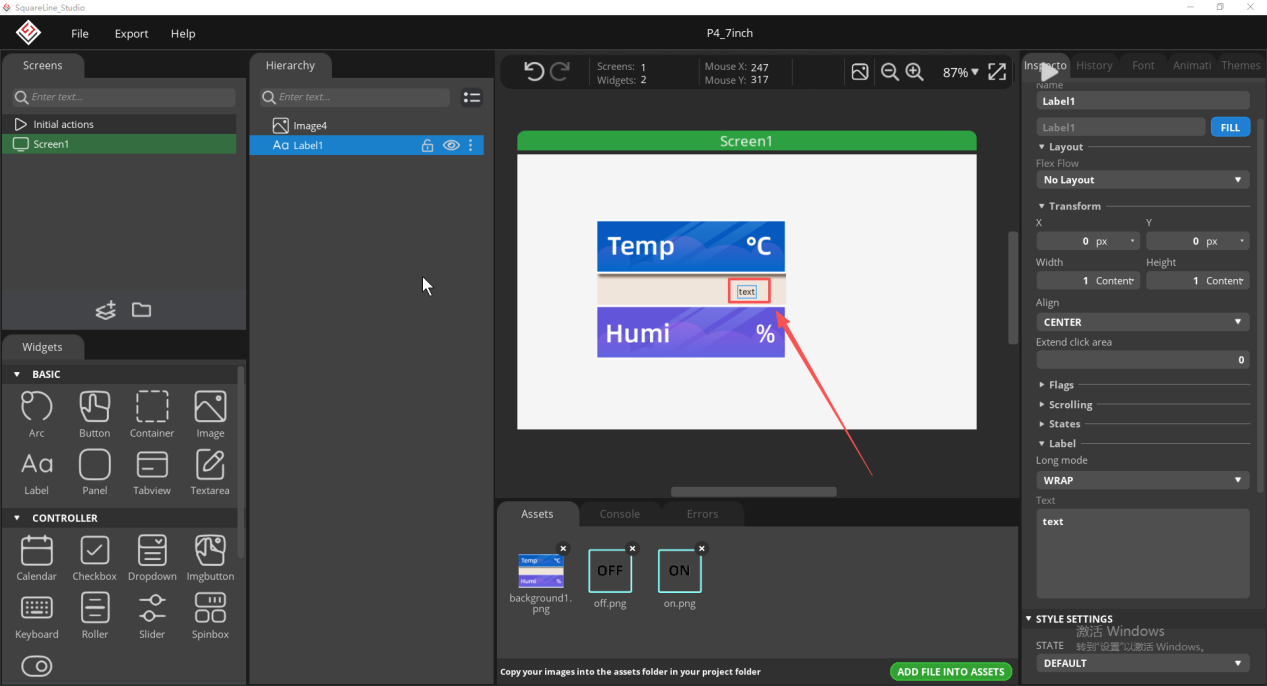
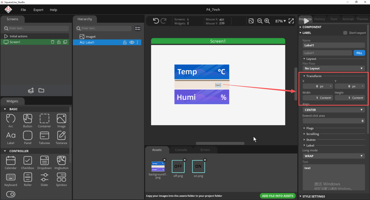
Drag the Label or enter coordinates in Transform so that the temperature value sits within the temperature area of the background image.
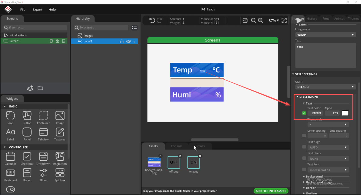
In STYLE (MAIN), set Text Color so that the text has sufficient contrast against the background.
In STYLE (MAIN), set Text Font; the example program uses Montserrat at size 40.
Choose a font size that you find appropriate.
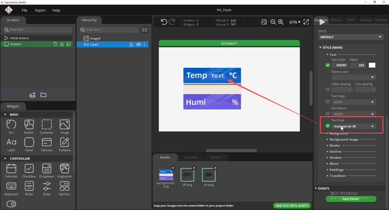
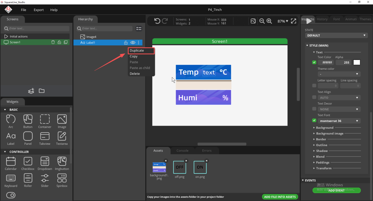
Duplicate the temperature Label to create the humidity Label, so that the two do not have inconsistent styles.
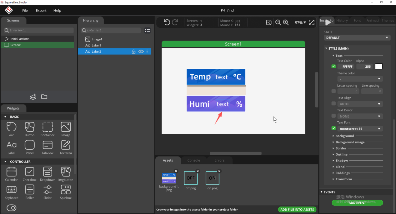
Adjust the position of the second Label so that it falls within the humidity display area.
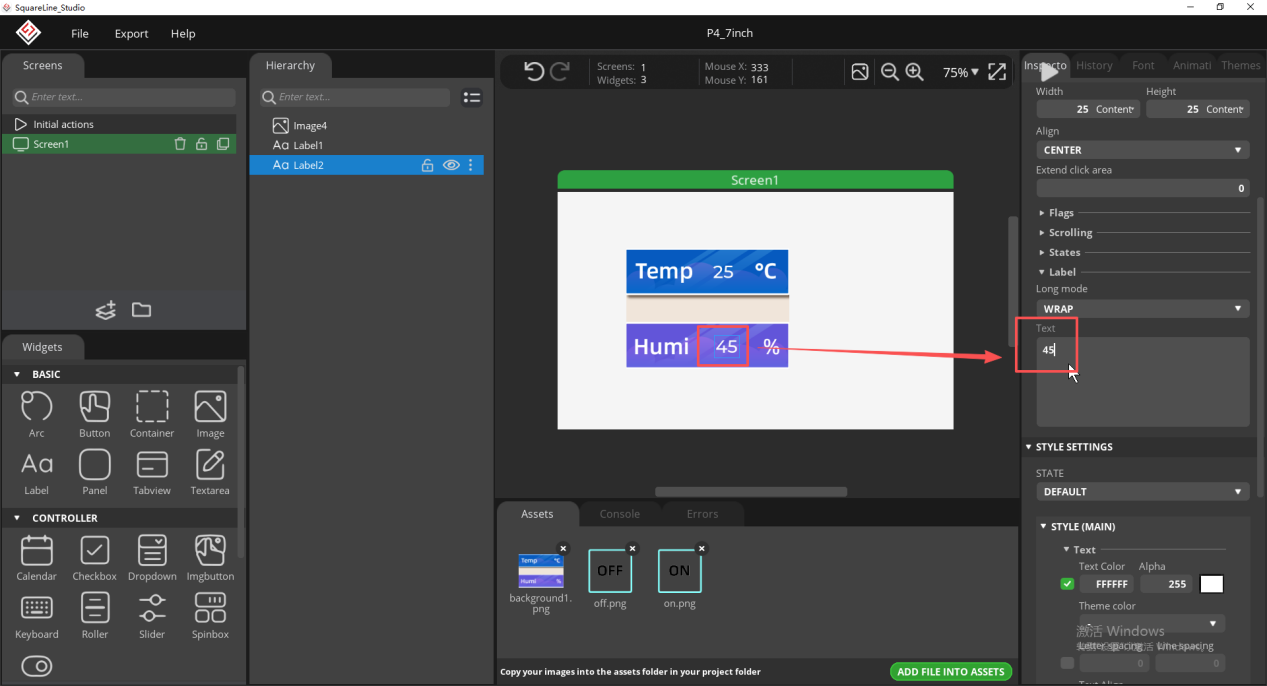
Modify the default text of both Labels and use temporary values to check alignment; after export, the program will replace them with sensor readings.
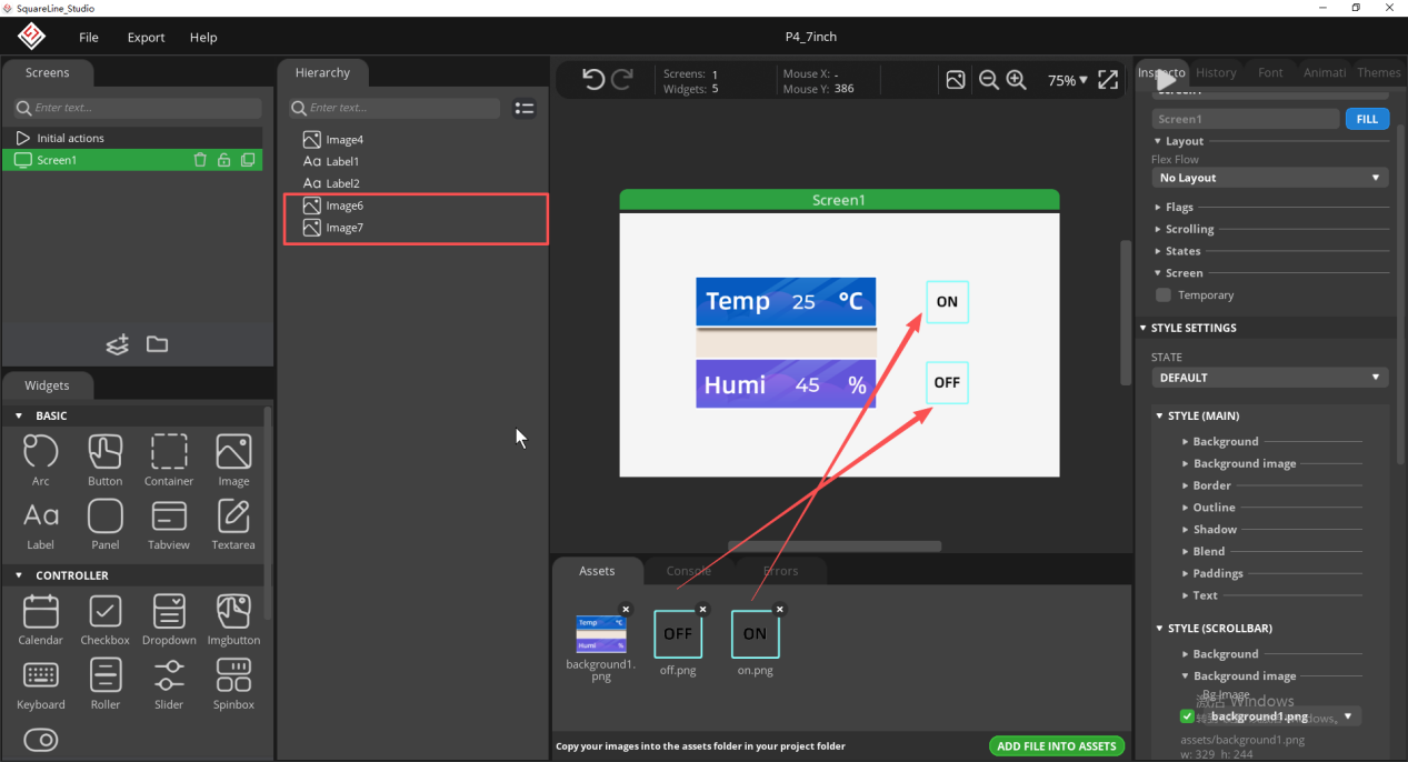
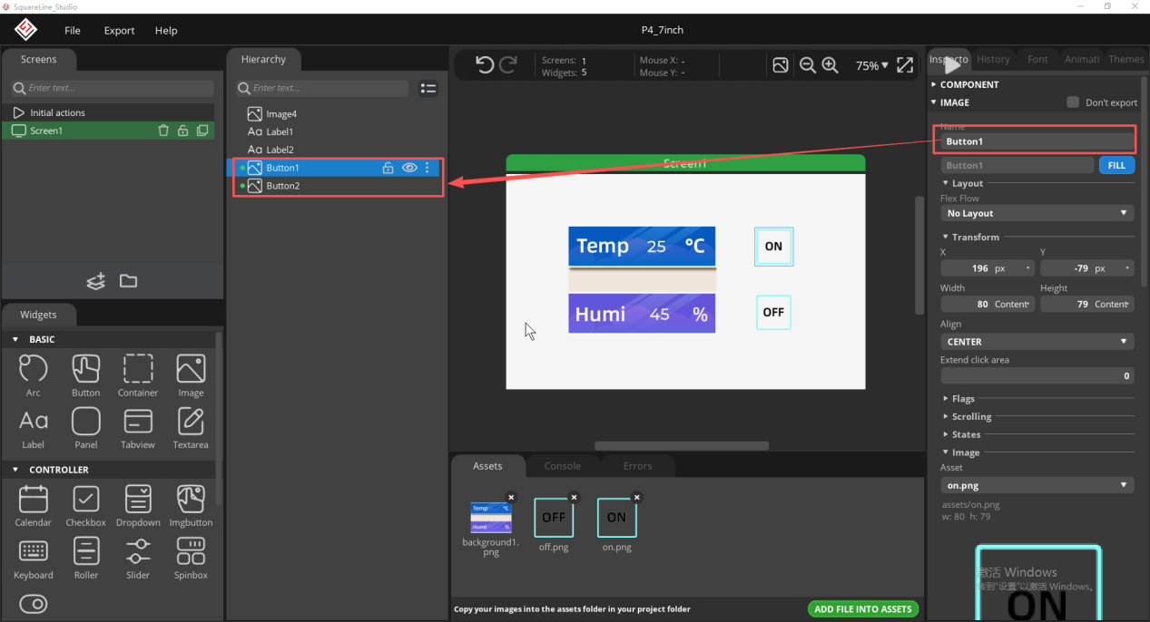
Add two image buttons as ON and OFF respectively, and name them strictly Button1 and Button2.
Check the size, position, and object names of both buttons to ensure their touch areas do not overlap, and keep the names as Button1 and Button2.
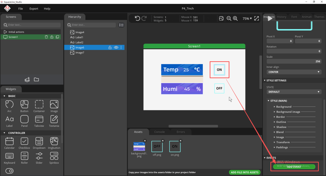
Select the ON button and click ADD EVENT to create a new event.
Set the trigger condition to clicked;
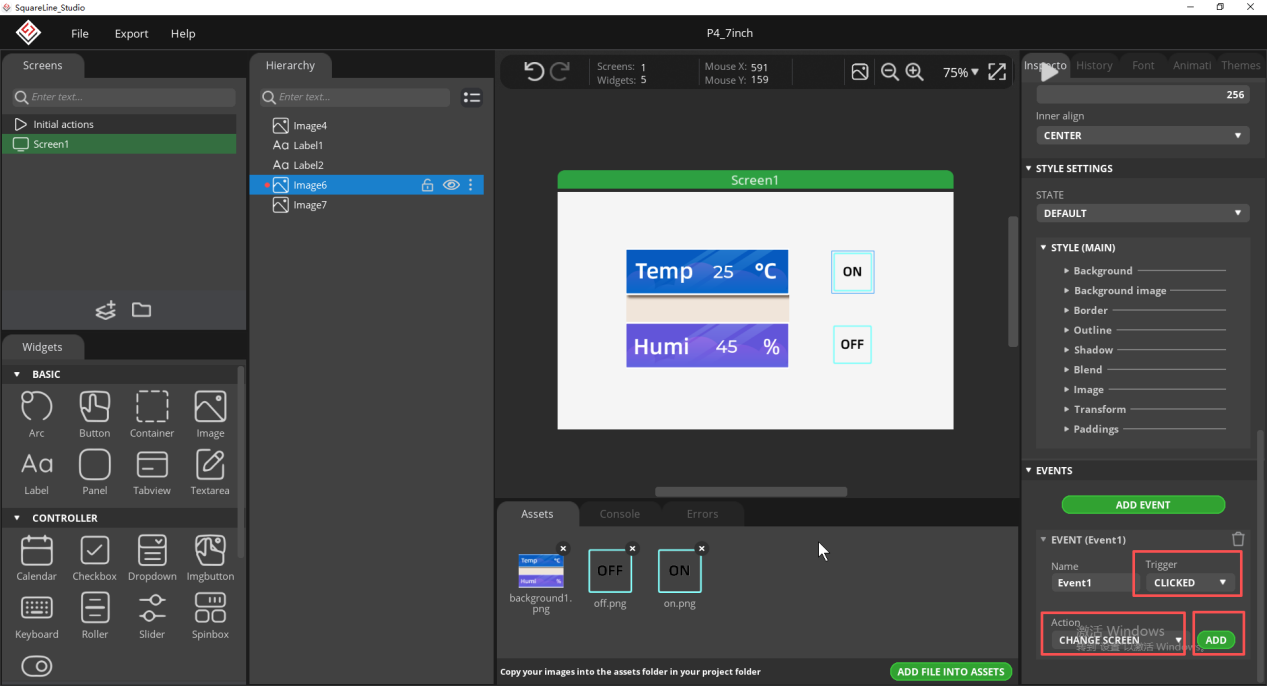
Action suggestion: select Call function
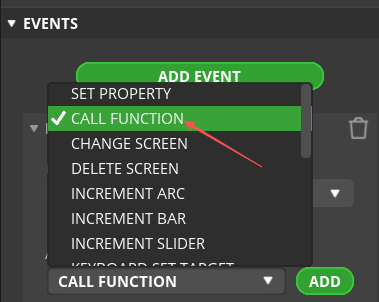
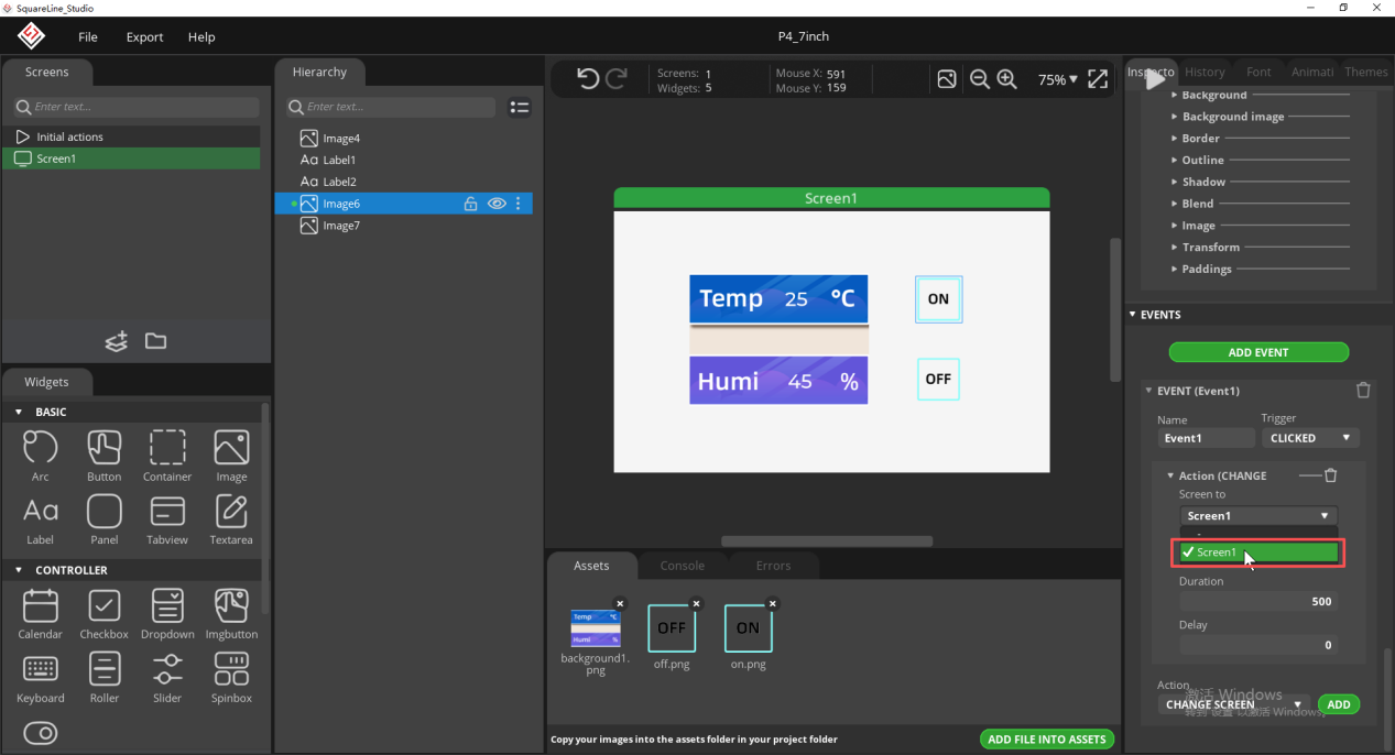
Switch to Screen1 following the source document example; later, in Python, replace the generated action with GPIO control.
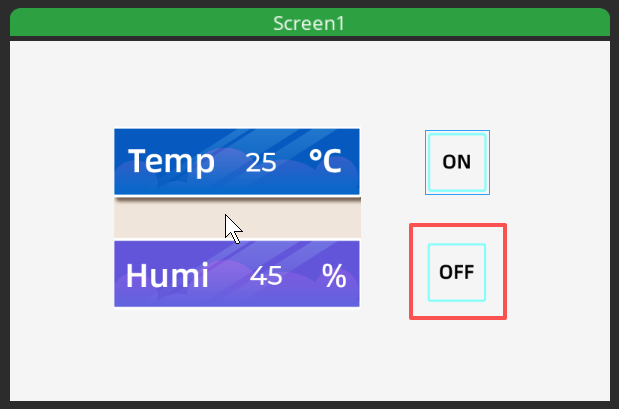
Repeat the same event configuration for the OFF button to ensure both controls export an event entry point.
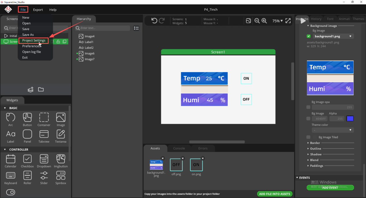
Open the export settings to prepare to generate the MicroPython UI assets.
Set the export directory and enter lvgl.h in the LVGL include path.
Set the export path for the files (set the path according to your own files).
Enter lvgl.h in the LVGL include path.
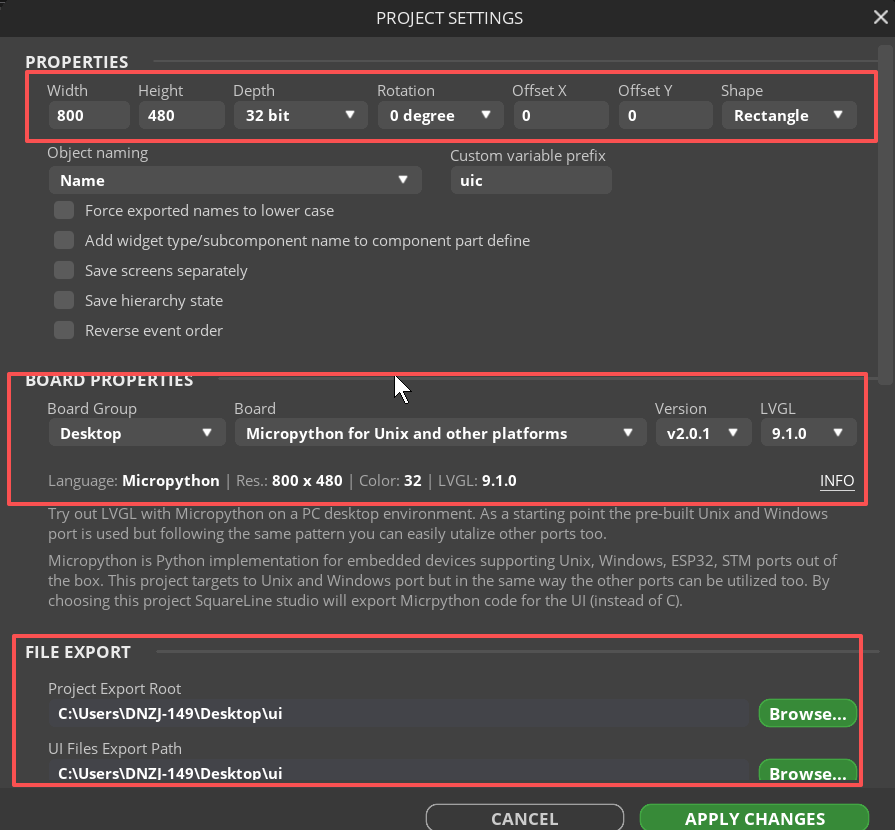
Recheck the export directory to avoid writing the generated files into the wrong project. 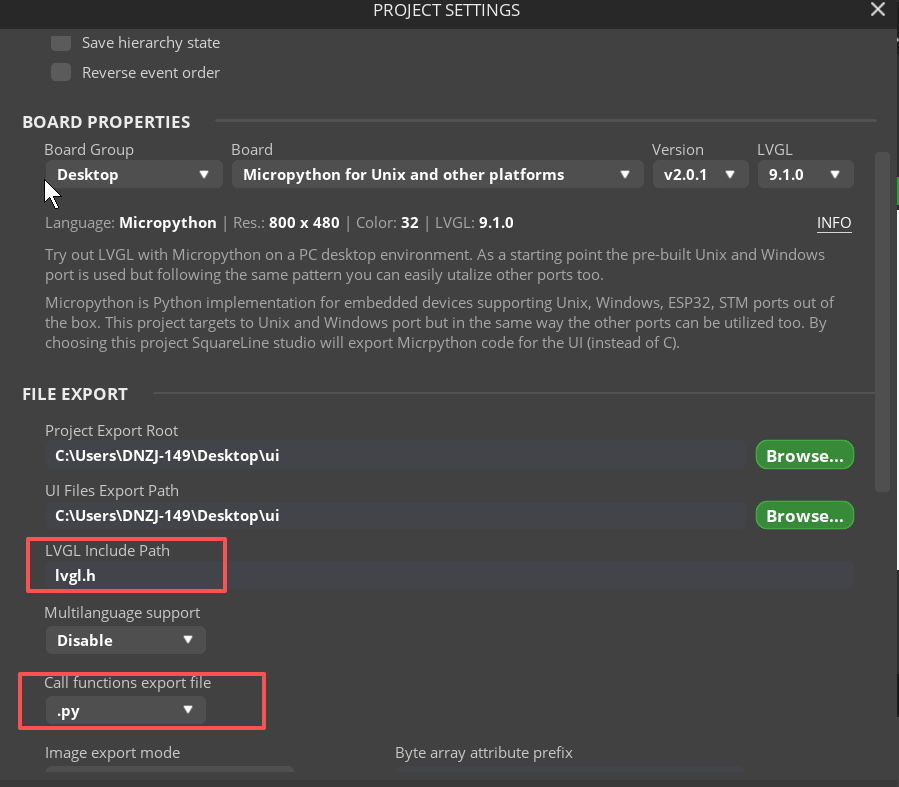
Click APPLY CHANGES to save the export configuration. 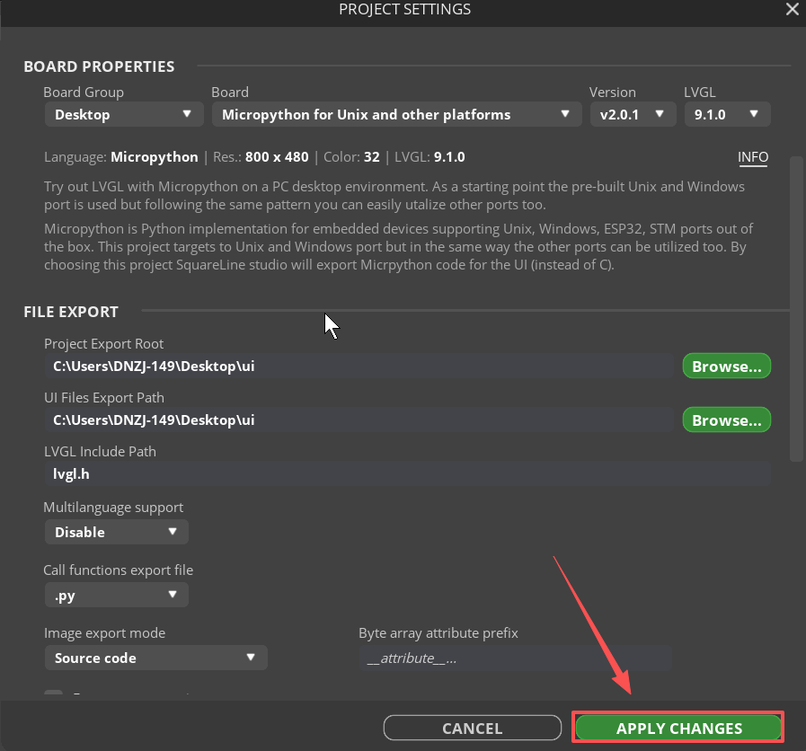
Execute the UI file export.
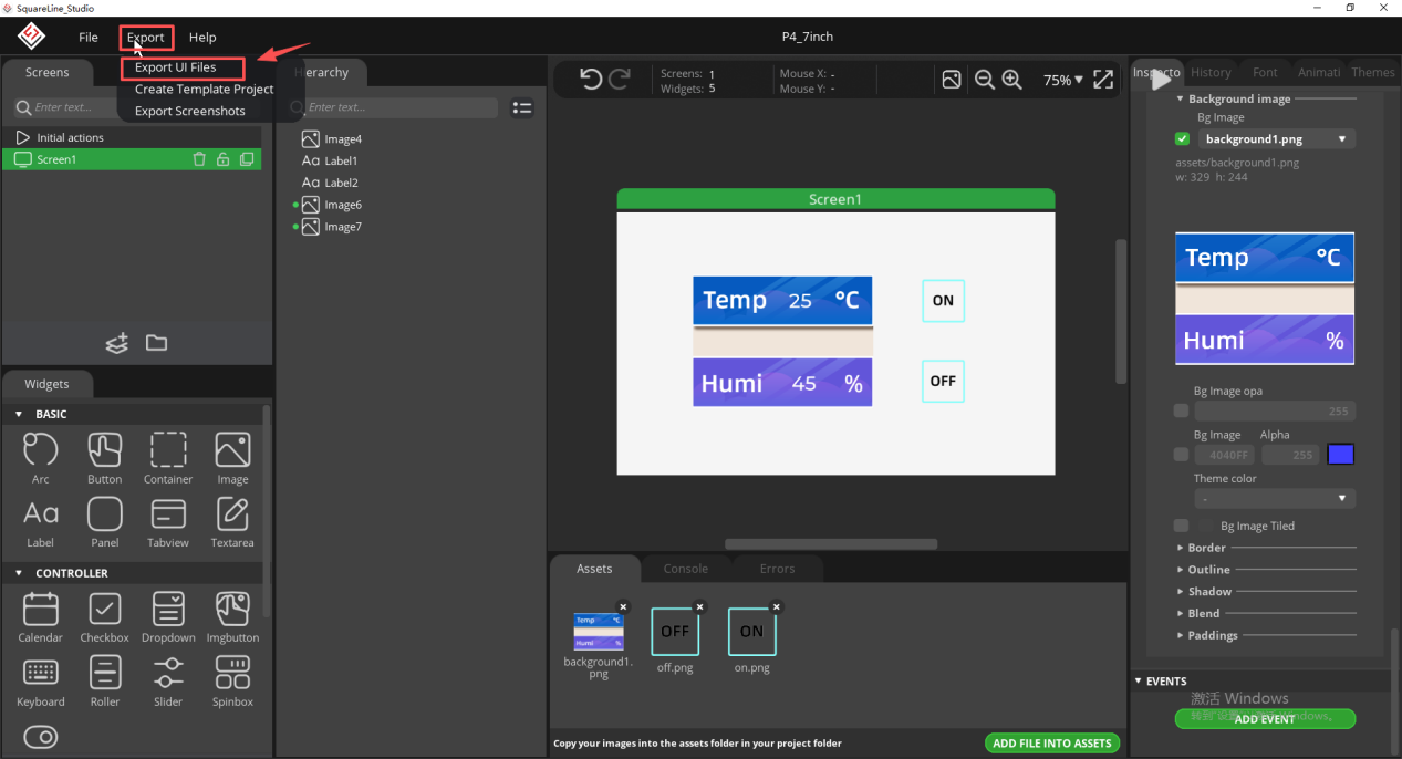
The UI file export is complete; we will only need the " ui_images.py " file. Next, we will learn the main program and how to use the Thonny IDE to upload the code to the development board.

5. Software Operation Steps
Please visit https://thonny.org/ and download the corresponding software version (the Windows version is used as an example here).
Note:
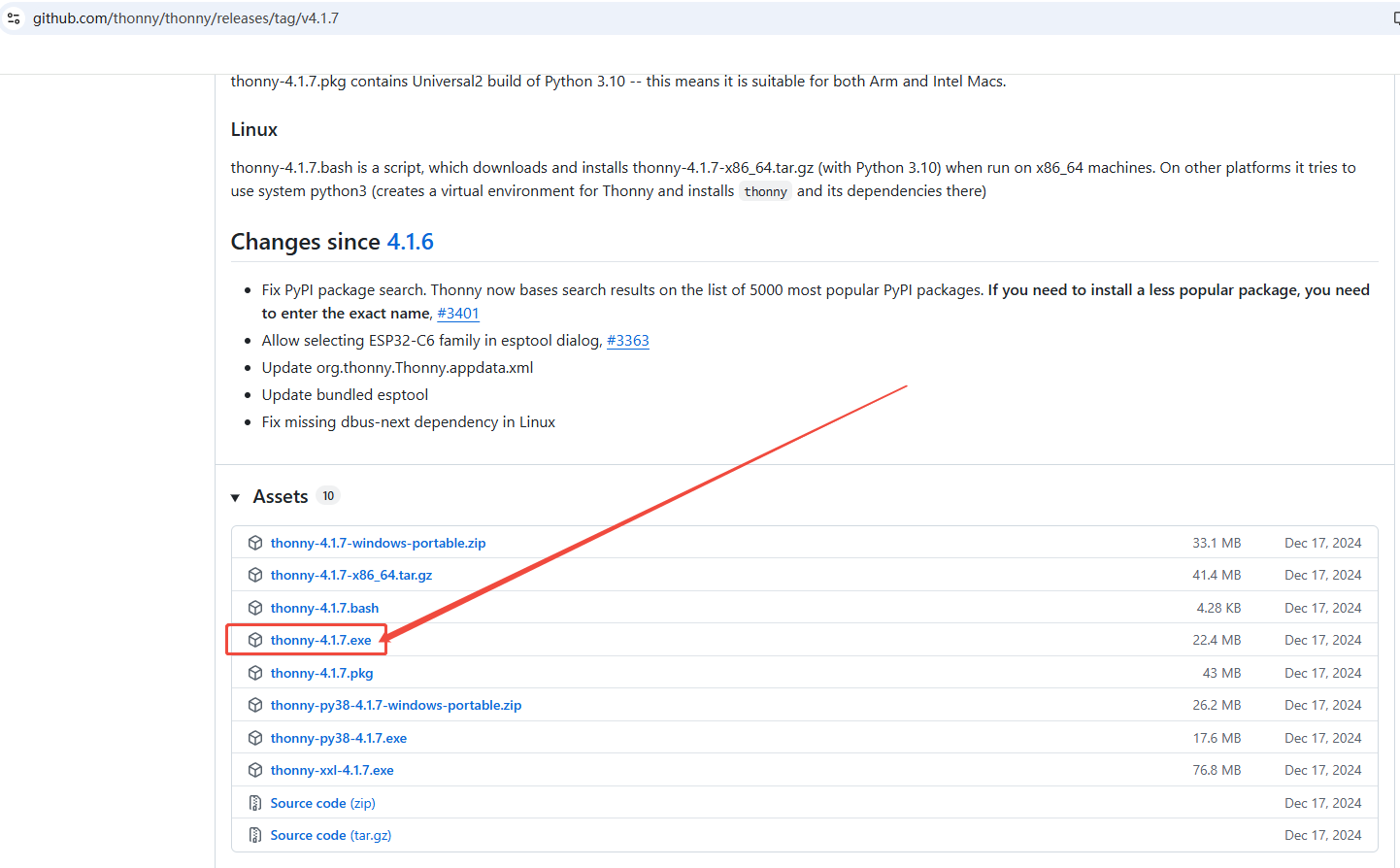
If the latest version of the editor fails to upload firmware or compile successfully, please try the stable version 4.1.7.
Download link: https://github.com/thonny/thonny/releases/tag/v4.1.7
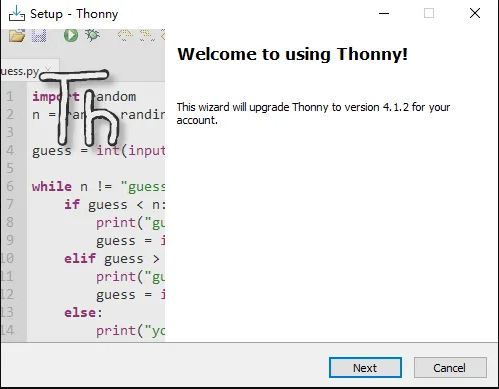
Run the installer and complete the installation, then launch Thonny.
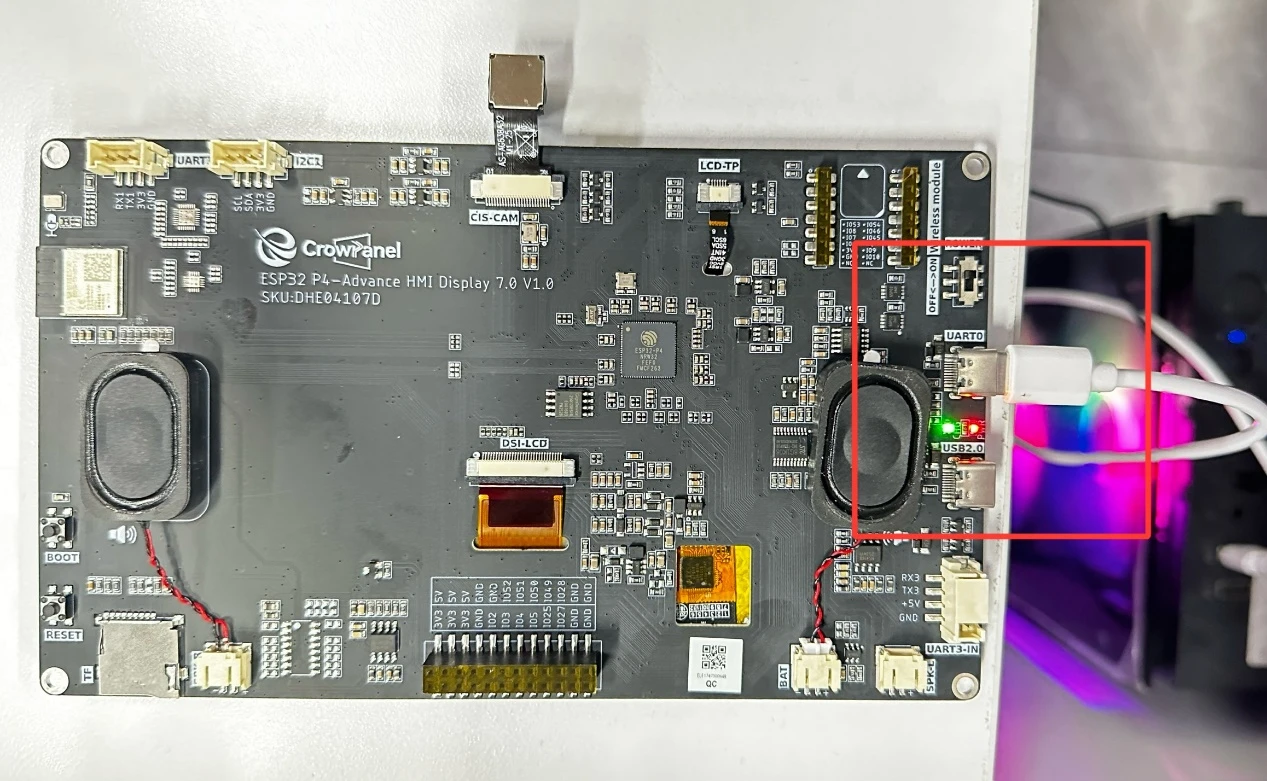
Connect the CrowPanel Advanced 7-inch ESP32-P4 HMI AI display to your computer using a USB cable.
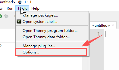
In Thonny, open Tools → Options in sequence.
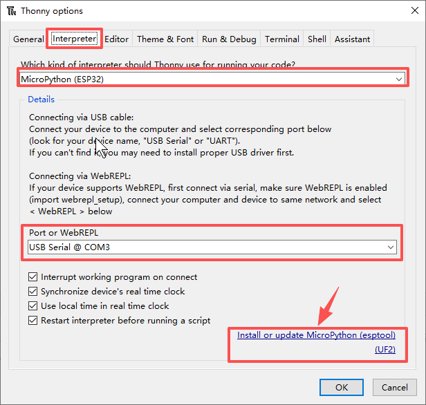
On the Interpreter page, select MicroPython (ESP32) and the corresponding serial port, then click Install or update MicroPython (esptool).
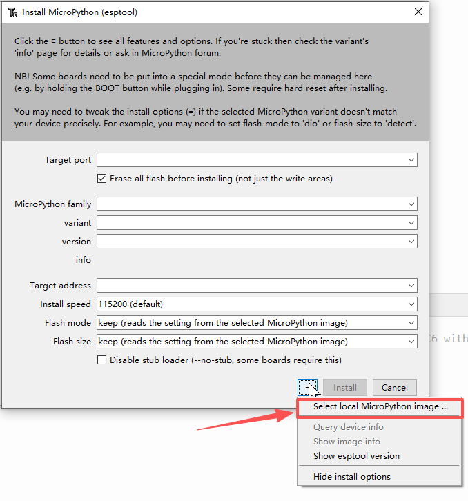
Click the icon with three horizontal lines, then click " Select local MicroPython image " , select
"lvgl_micropy_ESP32_GENERIC_P4-C6_WIFI-16_ELECROW_INCH7-9-10_1_V1_0.bin" and install it.
Please click the following link to download the bin file:
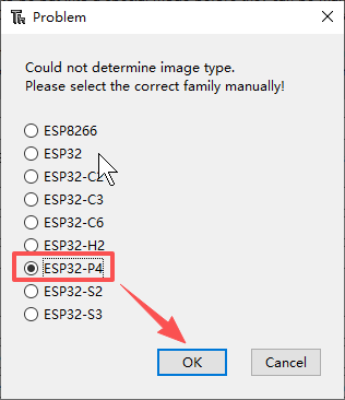
Select ESP32-P4 as the target chip.
After rechecking the serial port and flashing parameters, click Install; do not unplug the cable during flashing.
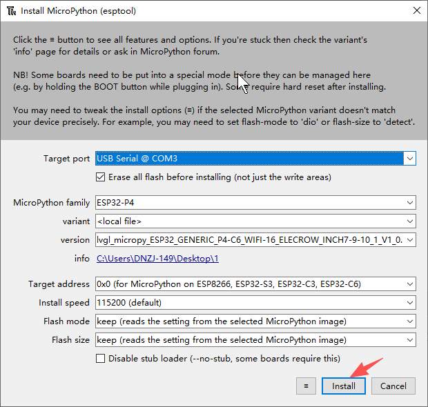
Wait for erasing, writing, and verification to complete; continue only after you see the success message.
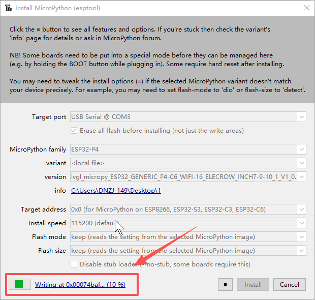
Confirm that the installation success page shows no error messages.
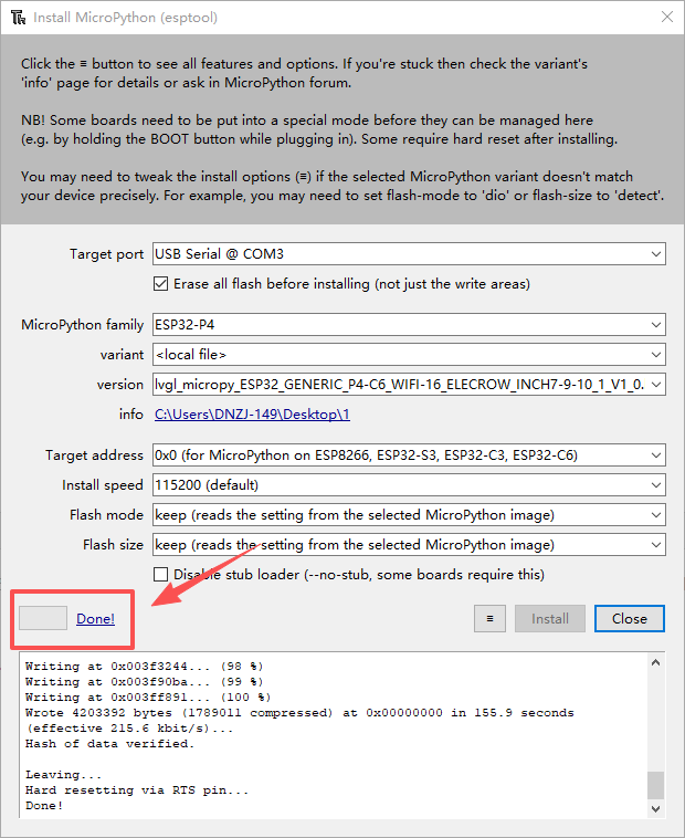
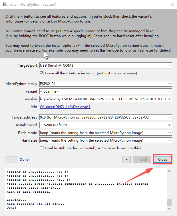
Click Close to close the firmware installation window.
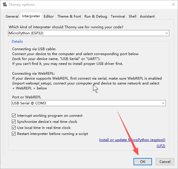
Return to the Options window and click OK to let the interpreter reconnect to the development board.
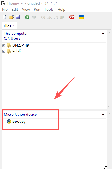
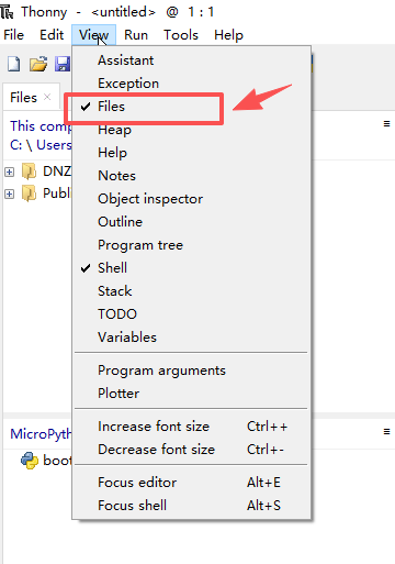
In the lower-left corner, confirm that MicroPython device and boot.py appear; if they do not, open View → Files.
If a " MicroPython device " window and a " boot.py " file appear in the lower left corner, the installation is successful.
If necessary, manually show the device file panel via View → Files.
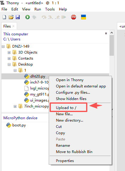
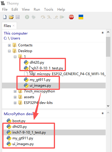
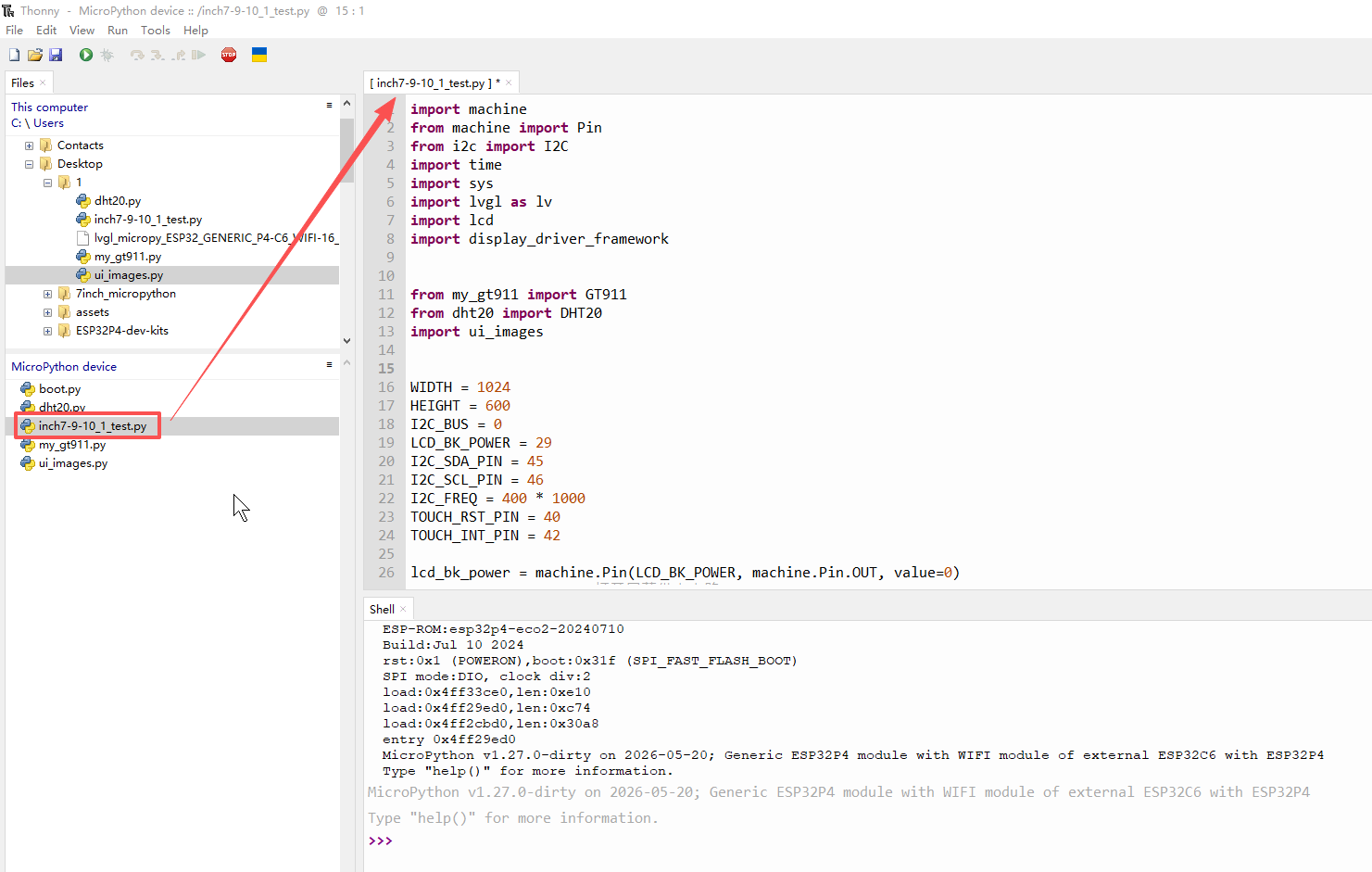
Upload inch7-9-10_1_test.py, my_gt911.py, dht20.py, and ui_images.py to the device root directory in sequence.
Wait for all files to finish copying and verify the file names and sizes on the device side; ui_images.py is large and takes longer to upload.
Double-click the device-side inch7-9-10_1_test.py to open the main program.
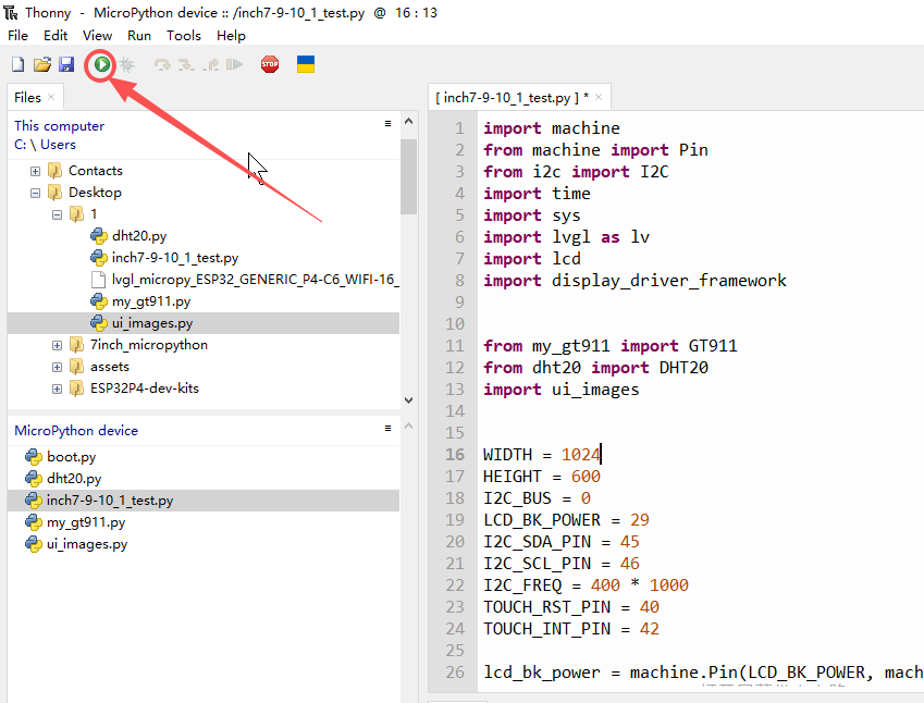
Click the green Run button; the console should first display the LCD, LVGL, and I2C initialization logs.
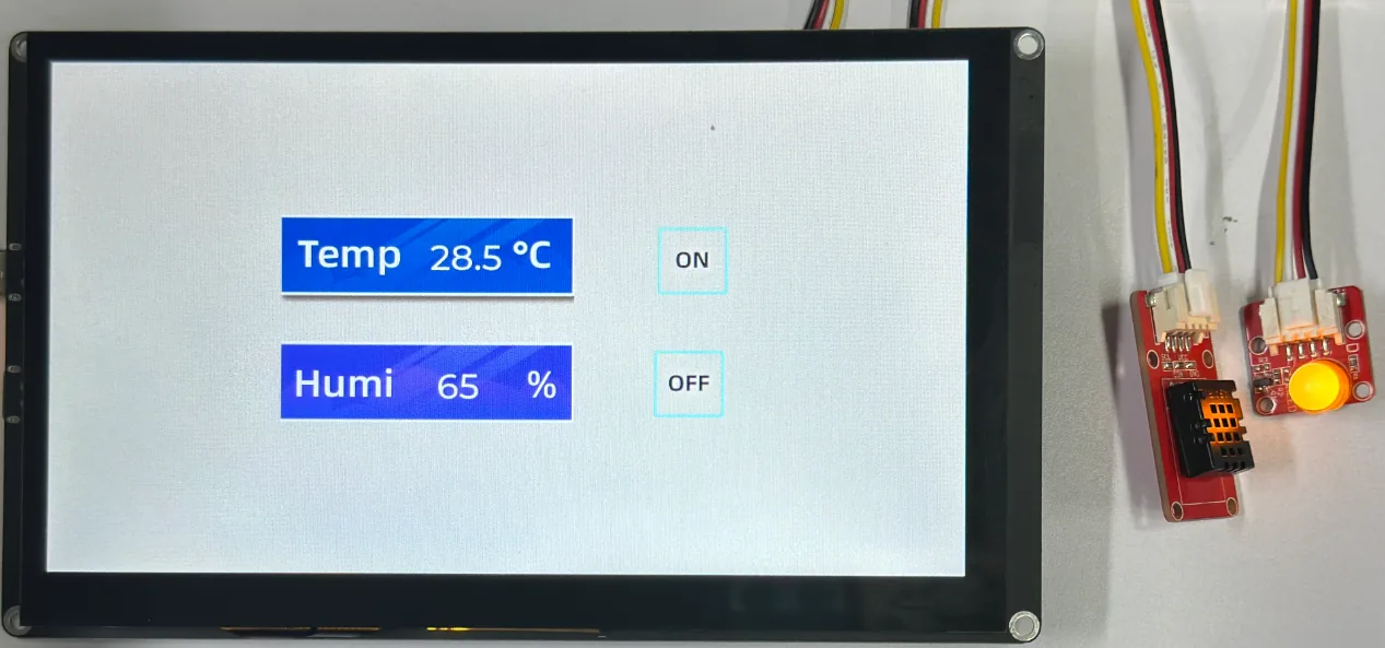
Observe the on-screen UI and temperature/humidity values, then touch the ON and OFF icons respectively to verify that the GPIO48 LED turns on and off.
6. Hardware Operation Steps
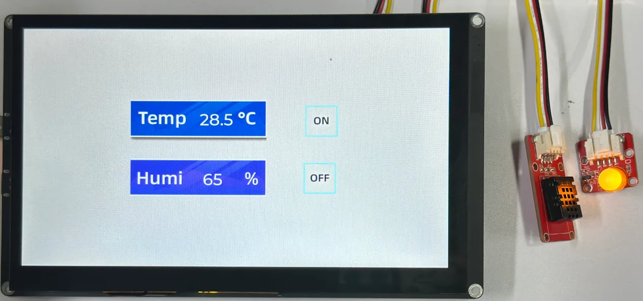
Disconnect the development board power, confirm that the DHT20 and LED experiment connections are secure, then use a USB cable that supports data transfer to connect the board to the computer and power it on. After the program runs, observe the temperature/humidity interface on the LCD and the GPIO48 LED; when touching the ON and OFF icons, the LED should light up and turn off respectively.
Safety note: Use your finger to operate the capacitive touchscreen; do not touch the screen with sharp or metallic objects. Do not unplug the USB cable while flashing or transferring files.
7. Key Code Explanation
7.1 GPIO48 and Touch Events
LED = Pin(48, Pin.OUT)

def Button1_eventhandler(event_struct):
    event = event_struct.get_code()
    if event == lv.EVENT.CLICKED and True:
        LED.value(1)

def Button2_eventhandler(event_struct):
    event = event_struct.get_code()
    if event == lv.EVENT.CLICKED and True:
        LED.value(0)
Both functions are executed only when LVGL dispatches button events. The CLICKED event filters out other events such as press and release; when GPIO48 outputs 1, the LED turns on, and when it outputs 0, the LED turns off. If the UI can be displayed but the LED does not respond, first check whether the button object is still bound to the corresponding callback, then check the control name and GPIO48.
Clicking the button changes the LED state: Button1 turns the light on, and Button2 turns the light off.
Note: If you did not name the UI elements Button1 and Button2 when creating them, you need to change the function names to the button names used when creating the UI.

7.2 Display Refresh and Double Buffering
lv.display_create(1024, 600) creates a display object that matches the screen resolution, with RGB888 occupying 3 bytes per pixel.
    def flush_cb(display, area, color_p):
        w = area.x2 - area.x1 + 1
        h = area.y2 - area.y1 + 1
        size_in_bytes = w * h * 3
        try:
            data_view = color_p.__dereference__(size_in_bytes)
            lcd.flush(area.x1, area.y1, area.x2, area.y2, data_view)
        except Exception as e:
            print(f"❌ LCD refresh exception: {e}")
        display.flush_ready()
flush_cb() calculates the data length based on the rectangular area provided by LVGL and sends it to the LCD via lcd.flush(), and must finally call display.flush_ready(); if omitted, LVGL will keep waiting, manifesting as the screen no longer updating.

7.3 Touch and Non-blocking Main Loop
First, create the LVGL input device using lv.indev_create() and set it to the POINTER type. Then, register the touch coordinate reading function of GT911 to LVGL by calling indev.set_read_cb(touch._get_coords). In this way, when the user touches the screen, LVGL will automatically obtain the touch coordinates detected by GT911 and determine which touchable control the user has clicked based on the coordinates, thereby triggering the corresponding button event.
    indev = lv.indev_create()
    indev.set_type(lv.INDEV_TYPE.POINTER)
    indev.set_read_cb(touch._get_coords)
The main loop adopts a non-blocking time judgment method. It obtains the current running time through time.ticks_ms() and uses time.ticks_diff() to determine whether it has been 1000ms since the last DHT20 reading. Only when 1 second has elapsed will the temperature and humidity data be read once and the interface updated. It does not use time.sleep(1) to block the program for a long time. During the waiting period for the sensor to sample again, the program continues to execute lv.tick_inc(5) and lv.timer_handler(), allowing LVGL to continuously handle interface refresh, touch input, and control events. Finally, a very short delay of time.sleep_ms(5) is used.
# Record the last sensor reading time
        last_dht_time = time.ticks_ms()

        print("Initialization completed, entering main loop...")

        # Run LVGL polling event loop
        while True:
            current_time = time.ticks_ms()

            # 1. Decouple sensor reading: read sensor every 1000 ms (1 second) without blocking UI
            if time.ticks_diff(current_time, last_dht_time) >= 1000:
                dht20.measure()
                temp = dht20.temperature()
                hum = dht20.humidity()

                ui_Label1.set_text(f"{round(temp, 1)}")
                ui_Label2.set_text(f"{round(hum)}")

                # print(f"temperature: {round(temp, 1)} C")
                # print(f"humidity: {round(hum)} %")

                last_dht_time = current_time

            # 2. LVGL heartbeat and event handling (very important)
            lv.tick_inc(5)         # Notify LVGL that 5 ms have passed
            lv.timer_handler()     # Handle redraw and touch events

            # 3. Very short sleep to ensure UI frame rate and touch responsiveness
            time.sleep_ms(5)
7.4 Companion File Responsibilities
This lesson requires four Python files on the device side: the main program handles hardware initialization and the event loop, my_gt911.py provides the touch driver, dht20.py provides temperature/humidity reading, and ui_images.py stores the image resources exported from SquareLine Studio. All four files must be uploaded together with their names unchanged.
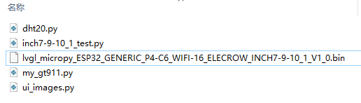
dht20.py : The driver file for the temperature and humidity sensor.
my_gt911.py : Driver file for the GT911 touchscreen.
ui_images.py : Image resource files required for the interface exported from SquareLine Studio.
lvgl_micropy_ESP32_GENERIC_P4-C6_WIFI-16_ELECROW_INCH7-9-10_1_V1_0.bin :
Elecrow packaged firmware that allows your Python scripts to display the LVGL UI, handle touch events, and interact with the DHT20 sensor on the LCD of the "CrowPanel Advanced 7inch ESP32-P4 HMI" .
inch7-9-10_1_test.py : This is the main program that runs the entire case study, and we will mainly explain this code file.
8. Experimental Phenomena and Acceptance
After the program starts, the console reports MIPI LCD, LVGL display, and I2C initialization completion in sequence; the LCD backlight turns on and displays the full UI. The temperature and humidity values update approximately once per second. After touching the ON icon, the GPIO48 LED lights up; after touching the OFF icon, the LED turns off. The interface should not freeze, display artifacts, or restart. If it can still respond stably after 10 consecutive clicks, it can be determined that the display, touch, and LED control chain is functioning normally.
Common issues: When the screen is black, first check the firmware, backlight, and LCD initialization logs; when the UI is displayed but touch is unresponsive, check the GT911, I2C scan results, and touch callback; when upload fails, close the software occupying the serial port and confirm that a data cable is used; when a MemoryError occurs, confirm that the specified firmware is used and that ui_images.py is not corrupted.