Lesson01_Arduino_LVGL_Rotary: 2.1-inch Rotary Display — Display, Touch, and Multi-page Interaction
1. Course Introduction
In this lesson, the Arduino IDE is used to drive the CrowPanel 2.1-inch HMI ESP32 Rotary Display. The project uses the Arduino GFX Library to control the 480 × 480 ST7701 circular IPS LCD, the Adafruit CST8XX Library to read capacitive touch coordinates, LVGL 9.1.0 to load the multi-page UI exported from SquareLine Studio, and FreeRTOS tasks and message queues to process the rotary encoder.
After the program is flashed and reset, the screen first plays a startup animation, then enters the main menu containing Volume, Temp, and Light. Swiping left or right or rotating the knob moves the selected item; touching a selected item or single-clicking the knob enters the detail page; on the detail page, dragging the arc or rotating the knob changes the value; double-clicking the knob or touching Return returns to the main menu. Volume adjusts the PWM of the GPIO 43 indicator light but produces no sound; Temp only updates the local temperature label; Light changes the screen backlight via GPIO 6 PWM.
The focus of this lesson is to verify the complete interaction chain consisting of the ST7701 RGB parallel display, PSRAM double buffering, CST8XX touch, PCF8574 expansion I/O, the LVGL multi-page UI, touch swiping, the knob message queue, and PWM backlight.
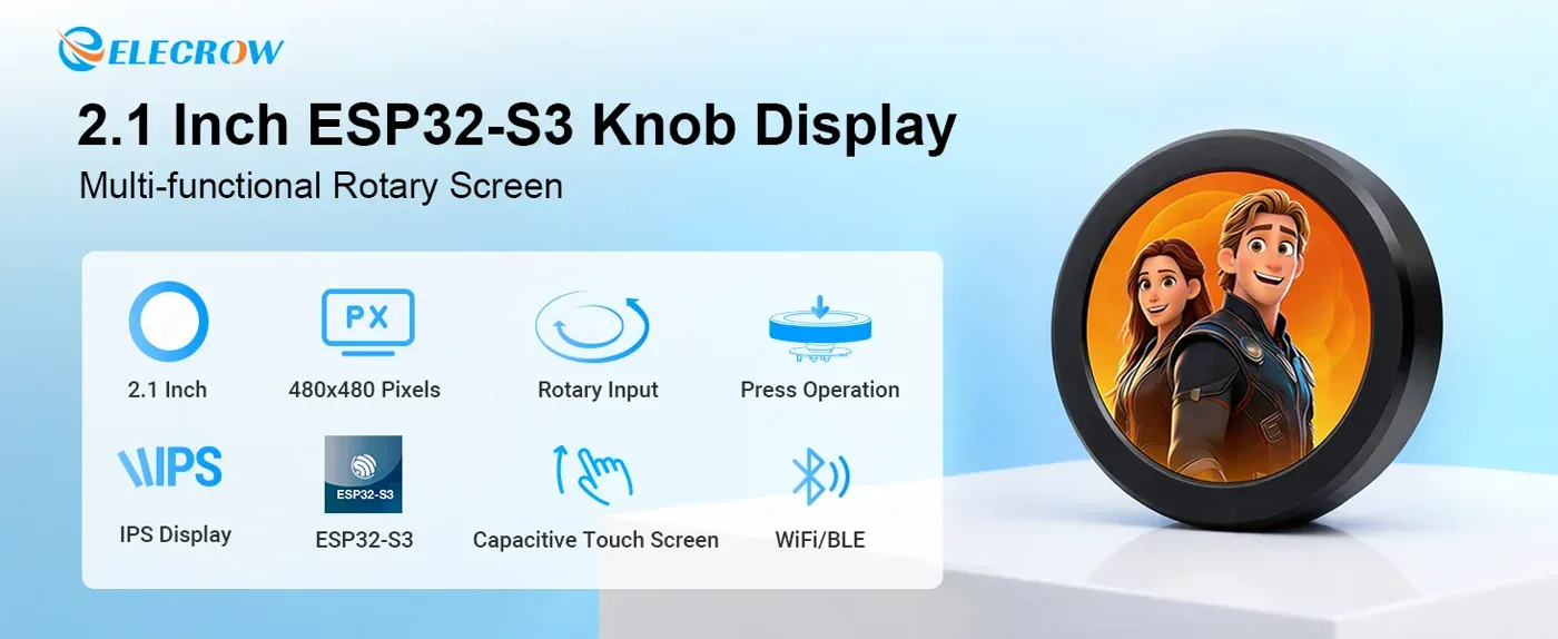
Product information: CrowPanel 2.1-inch HMI ESP32 Rotary Display
2. Learning Objectives
- Be able to configure the ESP32-S3, 16 MB Flash, OPI PSRAM, LVGL 9.1.0, and the course-specific partition.
- Be able to explain the relationship among the ST7701 RGB display, CST8XX touch, PCF8574, the knob, and LVGL.
- Be able to explain why RGB565 color conversion, PSRAM double buffering, and LVGL partial refresh affect display stability.
- Be able to compile and flash the complete project, and determine whether initialization succeeded based on the startup page, main menu, and serial log.
- Be able to use touch swiping, knob rotation, single-click, and double-click to complete page navigation and value adjustment.
- Be able to troubleshoot common issues based on the screen, backlight, GPIO 43 indicator light, and serial log.
3. Preparations
3.1 Hardware
- CrowPanel 2.1-inch HMI ESP32 Rotary Display 480 × 480, 1 unit.
- USB data cable that supports data transfer, 1 piece.
- Windows computer with the Arduino IDE installed, 1 unit.
The product has an onboard ESP32-S3, ST7701 circular LCD, CST8XX capacitive touch, rotary encoder, encoder button, PCF8574 I/O expander, and indicator light. This lesson requires no external sensors.
3.2 Software and Versions
| Software or Component | Verified Version | Purpose |
|---|---|---|
| Arduino IDE | 2.3.4 | Open, compile, and upload the project |
| ESP32 by Espressif Systems | 3.3.8 | ESP32-S3 Arduino Core |
| LVGL | 9.1.0 | GUI, animations, and input events |
| GFX Library for Arduino | 1.6.7 | ST7701 and RGB Panel driver |
| Adafruit CST8XX Library | 1.1.1 | Capacitive touch reading |
| PCF8574 Library | 2.3.7 | LCD, touch, and knob button expansion I/O |
| Adafruit BusIO | 1.16.2 | CST8XX communication dependency |
The UI-generated code uses the LVGL 9 API and requires LV_COLOR_DEPTH to be 16.
Course code:
CrowPanel 2.1-inch Arduino Examples
3.3 Project Files That Must Be Retained
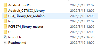
RotaryScreen_2_1/RotaryScreen_2_1.ino: the main program for this lesson.libraries/UI/: the 5 pages, image resources, and helper functions exported from SquareLine Studio.libraries/lvgl/: LVGL 9.1.0.libraries/GFX_Library_for_Arduino/: ST7701 and ESP32 RGB Panel drivers.libraries/Adafruit_CST8XX_Library/andlibraries/Adafruit_BusIO/: touch driver and its dependencies.libraries/PCF8574_library-master/: PCF8574 expansion I/O driver.libraries/lv_conf.h: LVGL configuration.ui_project/SLS_2_1v2-20250807/SLS_480v2/SLS480v2.spj: the editable 480 × 480, LVGL 9.1.0 UI project.elecrow_s3.csvpartition file and the correspondingboards.txtmenu configuration.
Do not copy only the .ino. When libraries/UI/ is missing, ui.h, the page objects, and image resources will fail to participate in compilation.
4. Software Operation Steps
Step01: Install ESP32
Arduino IDE installation guide: Get Started with Arduino IDE
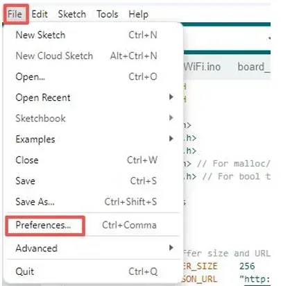
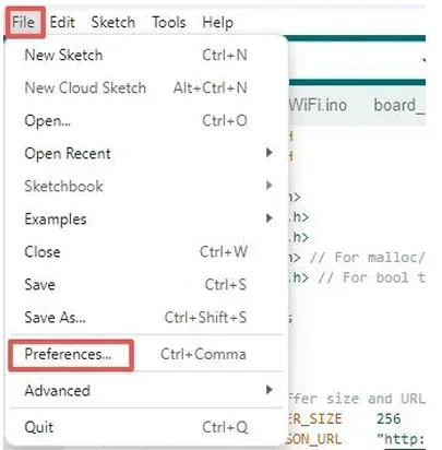
After installing the Arduino IDE, open File > Preferences.
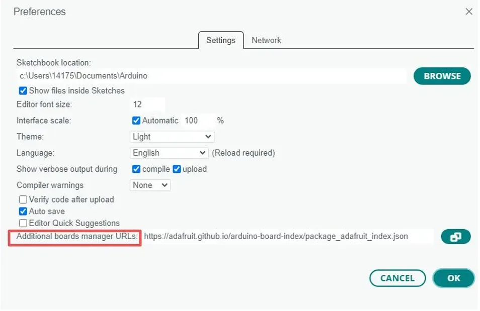
Find Additional Boards Manager URLs.
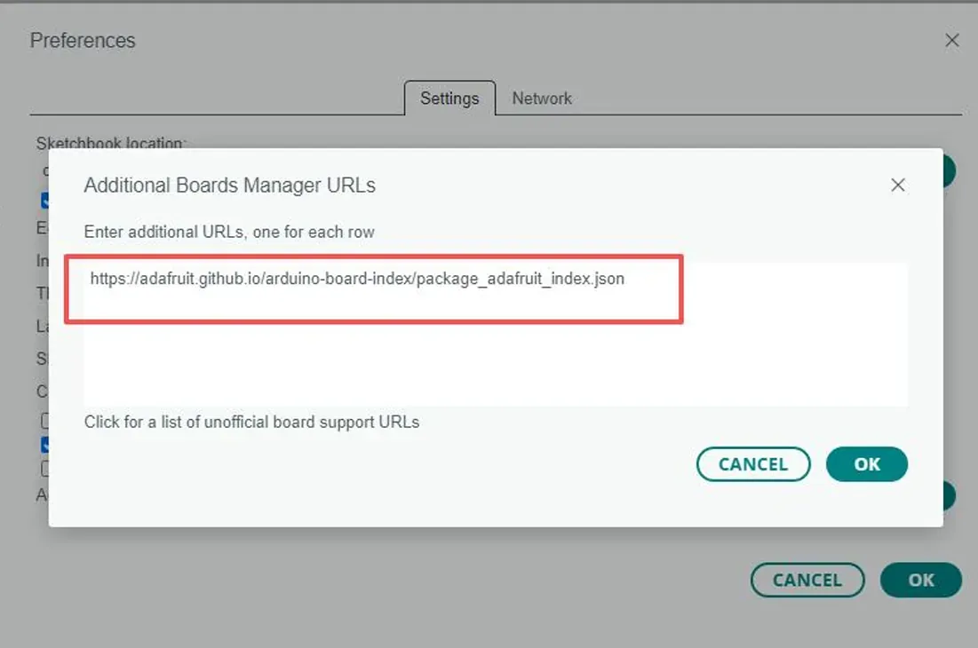
Add the following address and save:
https://adafruit.github.io/arduino-board-index/package_adafruit_index.json
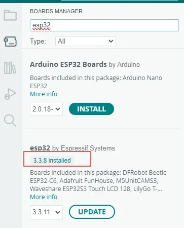
On the left, open Boards Manager, search for esp32, find esp32 by Espressif Systems, select 3.3.8, and install. If installed is already shown, do not reinstall.
Step02: Import Library Files
Open File > Preferences and view Sketchbook location.
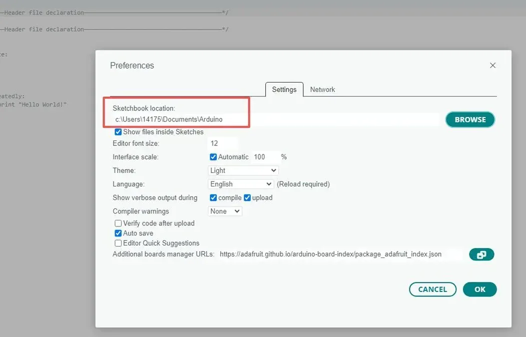
Open this path in the file system. If there is no libraries folder, create one.
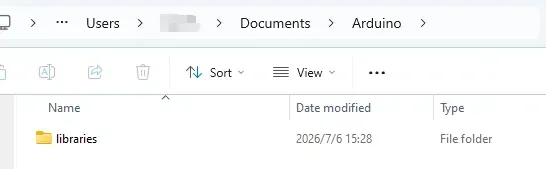
Confirm that the required Arduino libraries are present.
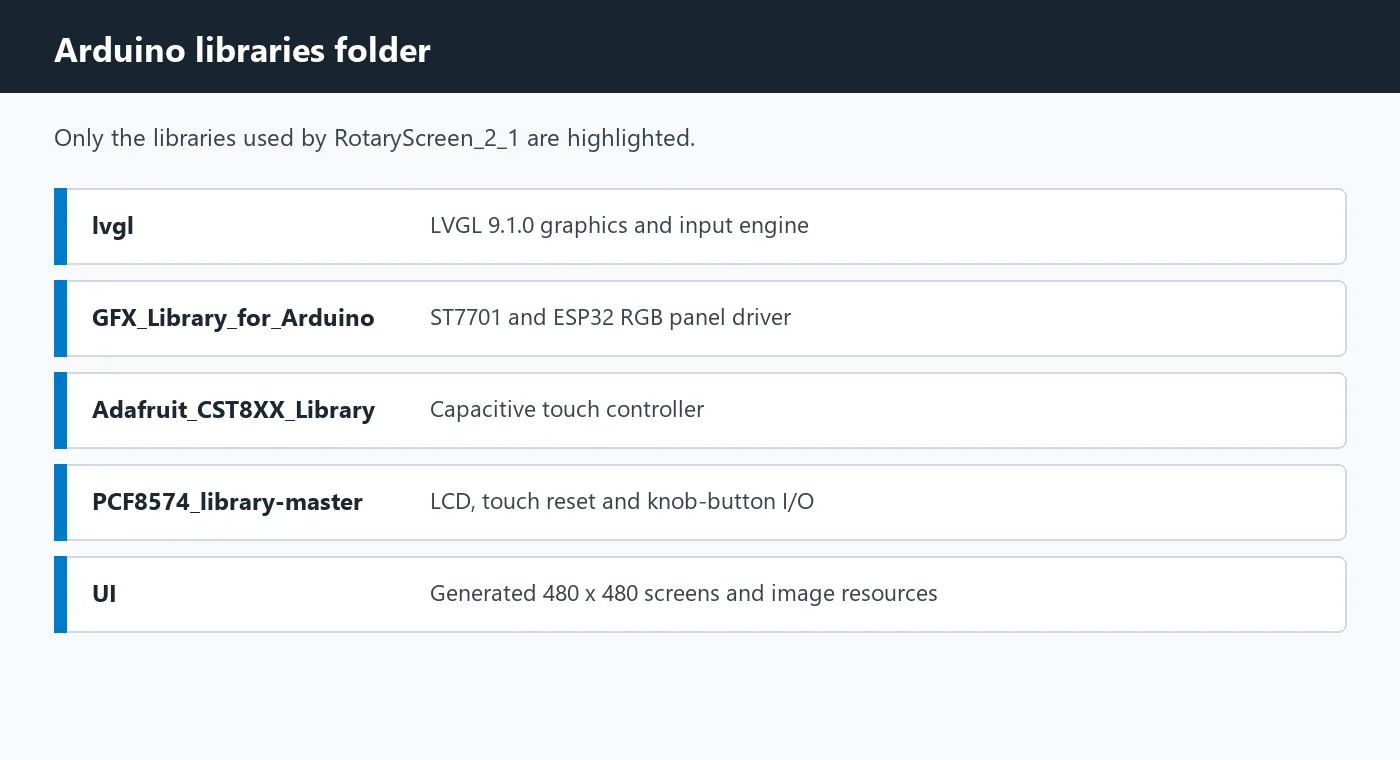
Our project's library file link:
Copy the folders from the course-provided libraries directory into the libraries folder of your local Sketchbook.
After determining the location where the library files are stored, copy all the library files contained in the downloaded "libraries" folder to the "C:\Users\Username\Documents\Arduino\libraries" folder on your local computer.
For example: (refer to the method shown in the image below, and copy the libraries you need to this path)
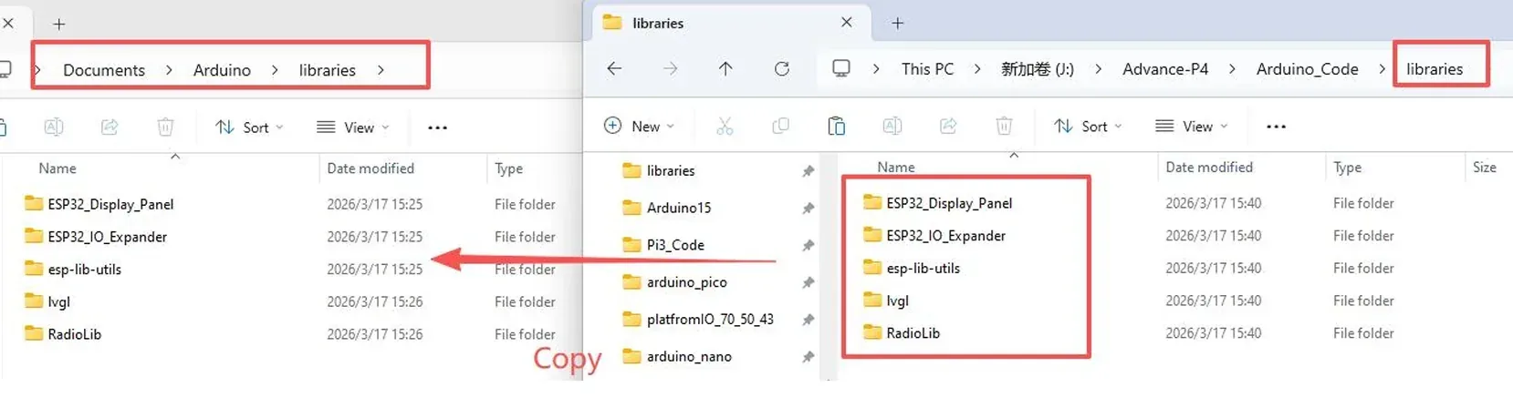
Library import guide: Arduino IDE Library Import Guide
Note: Restart the Arduino IDE after copying is complete. If the compilation log indicates that multiple libraries with the same name exist, confirm that the version and path actually used are those required by the course.
Step03: Export UI Files from SquareLine Studio
You can click the link below to download the SquareLine Studio project we provide.
SquareLine Studio operation guide:
https://www.elecrow.com/wiki/Get_Started_with_SquareLine_Studio.html
SquareLine Studio supports exporting UI projects for the LVGL graphics library used in this lesson.
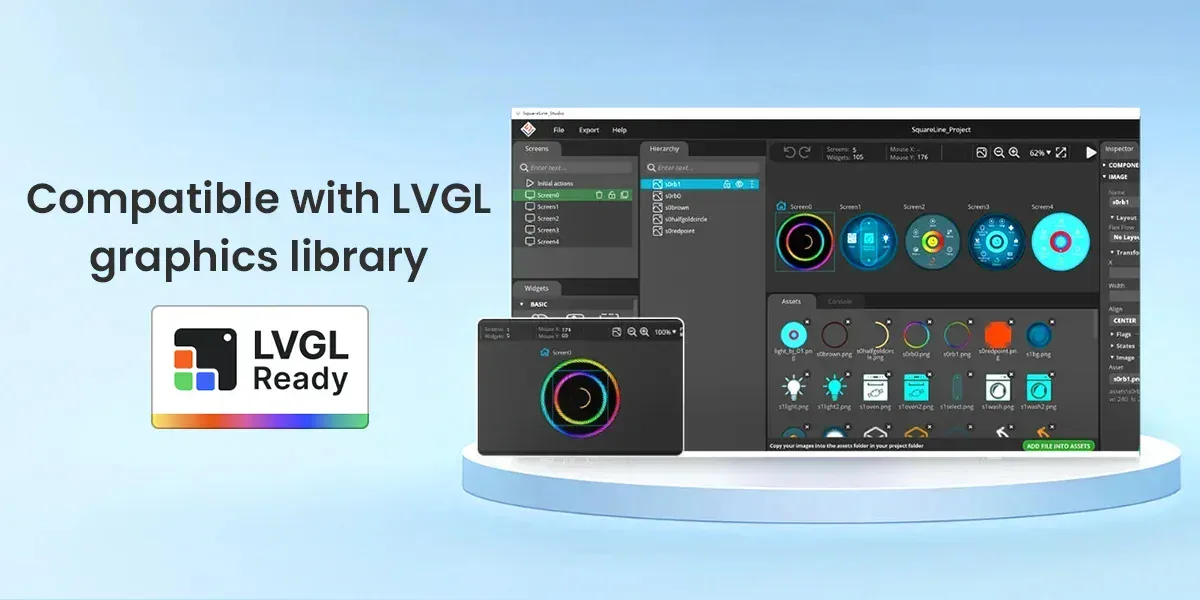
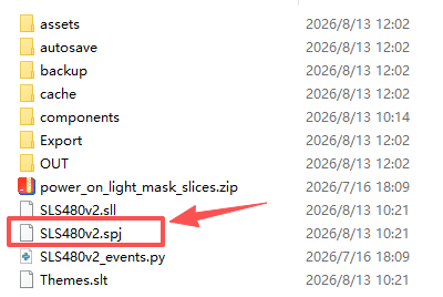
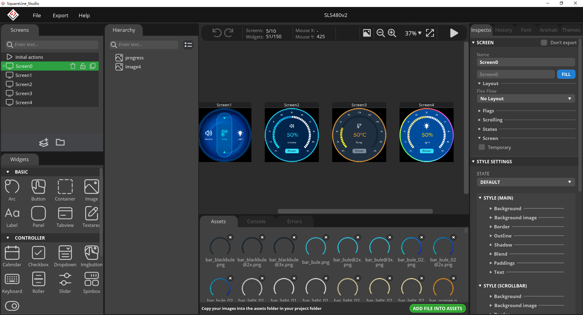
After downloading SquareLine Studio, click Import.
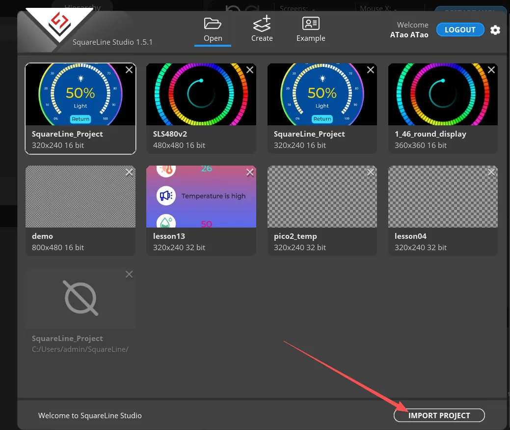
Export our project, and you will be able to see the specific UI information.
Step04: Expand the Partition Table
This project contains a large number of 480 × 480 RGB565 image resources, and the generated application firmware has been verified to be approximately 6.0 MB. The 3 MB Huge APP partition that ships with the ESP32 Core is insufficient, so the project-provided elecrow_s3 partition must be used.
Because the Arduino IDE code for the rotary display integrates the UI files generated by SquareLine Studio, the overall project size is relatively large. The partition tables currently provided in the ESP32 library are insufficient to support the operation of the entire project, so the partition table needs to be expanded.
The partition table content we provide can be downloaded first:
After downloading the partition table file, open the installation path of your local ESP32 Arduino Core.
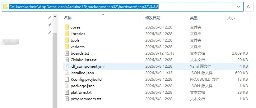
Open the boards.txt in the partition table file we provide via the link above and copy its contents.
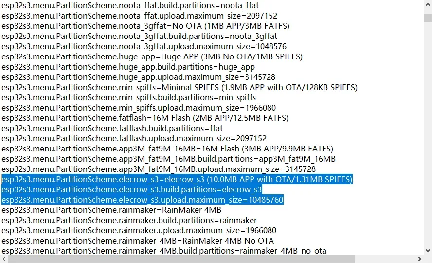
esp32s3.menu.PartitionScheme.elecrow_s3=elecrow_s3 (10.0MB APP with OTA/1.31MB SPIFFS)
esp32s3.menu.PartitionScheme.elecrow_s3.build.partitions=elecrow_s3
esp32s3.menu.PartitionScheme.elecrow_s3.upload.maximum_size=10485760
Then open the boards.txt in your local path.
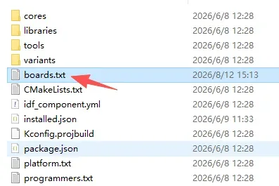
Copy the above content to the corresponding location; do not place it randomly. You may refer to the position shown in the image.
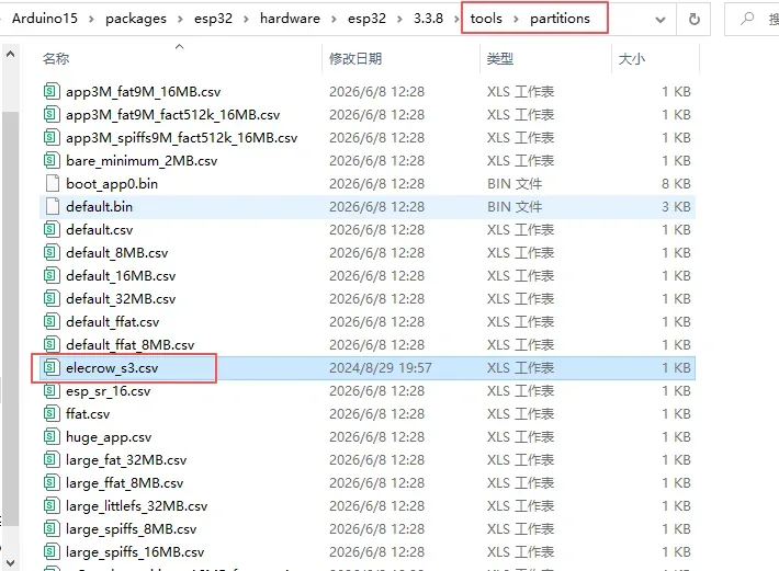
Copy the project-provided elecrow_s3.csv into the Core's tools/partitions directory, then fully close and reopen the Arduino IDE.
Upgrading or reinstalling the ESP32 Core may overwrite these two modifications. If the elecrow_s3 menu disappears, this step must be performed again.
Step05: Open the Code, Set Parameters, and Upload
The code link has been provided above; please download it.
Then double-click this ino file to open the entire project.

Confirm that the libraries and UI actually called by the main code exist.
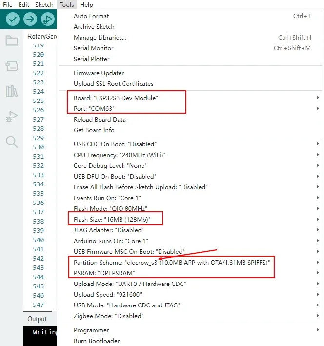
Double-click RotaryScreen_2_1.ino. Set the following in the Tools menu:
- Board:
ESP32S3 Dev Module - CPU Frequency:
240MHz (WiFi) - Flash Mode:
QIO 80MHz - Flash Size:
16MB (128Mb) - PSRAM:
OPI PSRAM - USB CDC On Boot:
Enabled - USB Mode:
Hardware CDC and JTAG - Upload Mode:
UART0 / Hardware CDC - Upload Speed:
921600 - Partition Scheme:
elecrow_s3
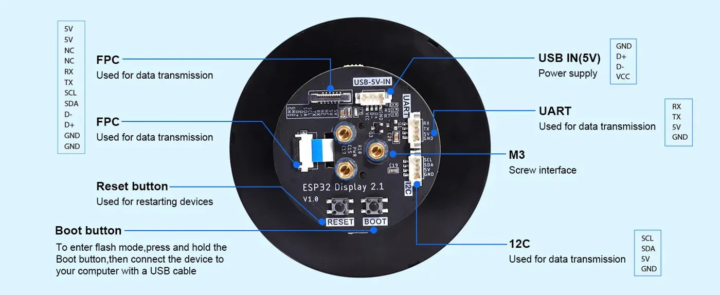
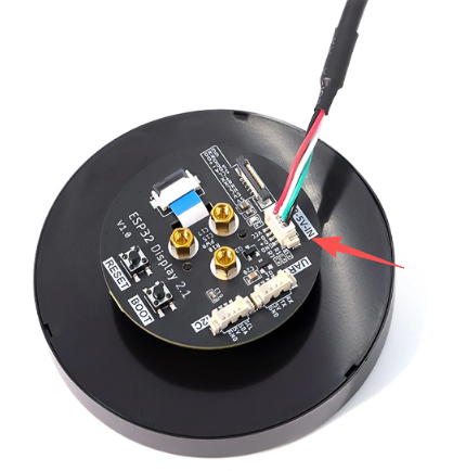
Connect the device using a USB data cable. In the back interface diagram, the course flashing port is USB IN; do not hot-plug the FPC cable while powered on.
Select the newly appeared serial port in Tools > Port. The port number varies by computer; do not copy the COM number shown in the example.
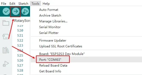
Click Verify first. After successful compilation, click Upload.
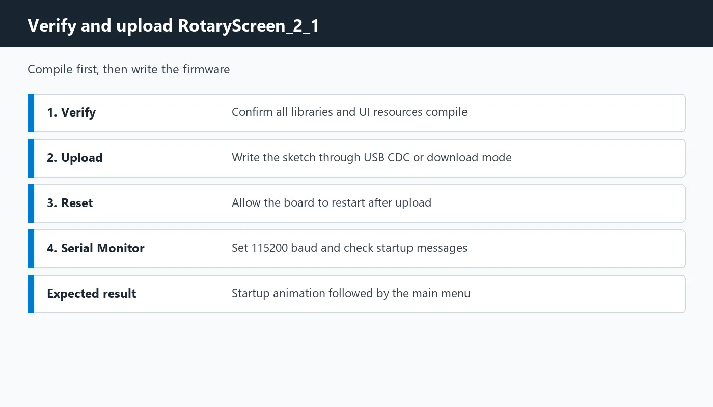
If the device does not automatically enter download mode, disconnect the USB, hold down the BOOT button on the back, reconnect the USB, release it after the port is recognized, and upload again.
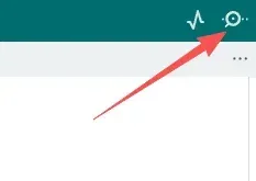
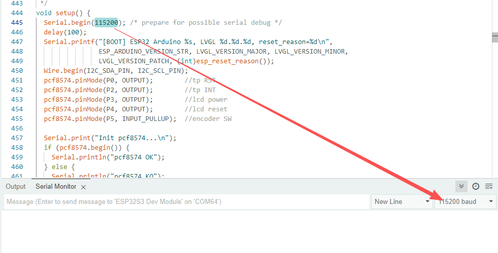
After the upload completes, open the Serial Monitor in the upper right corner.
Set the baud rate to 115200 and press RESET once. A normal log should include the version, PCF8574 initialization, touch recognition, and Settings completed.. The port must be reselected when the USB CDC re-enumerates.
5. Hardware Operation Steps
Step01:
With power off, check the USB IN, RESET, BOOT, UART, I2C, and FPC interfaces. This lesson uses only USB IN to connect to the computer; do not apply 5 V to the signal pins.
Use a USB cable that supports data transfer to connect the CrowPanel 2.1inch-HMI ESP32 Rotary Display to the computer.
Step02:
After powering on, wait for the startup animation to finish. After entering the main menu, rotate the knob by hand and observe whether the blue selected item moves among Volume, Temp, and Light.
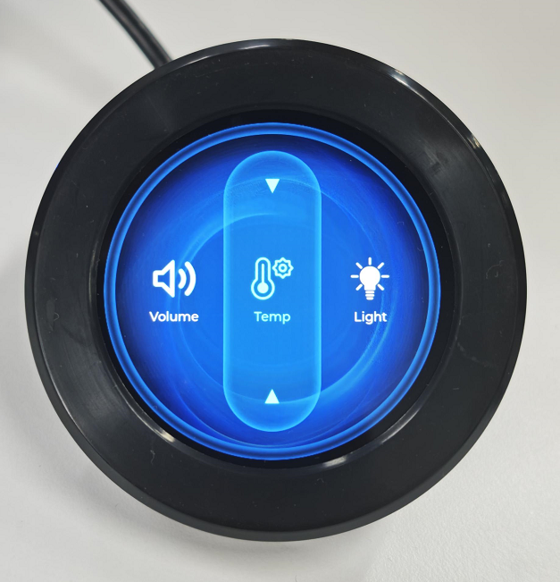
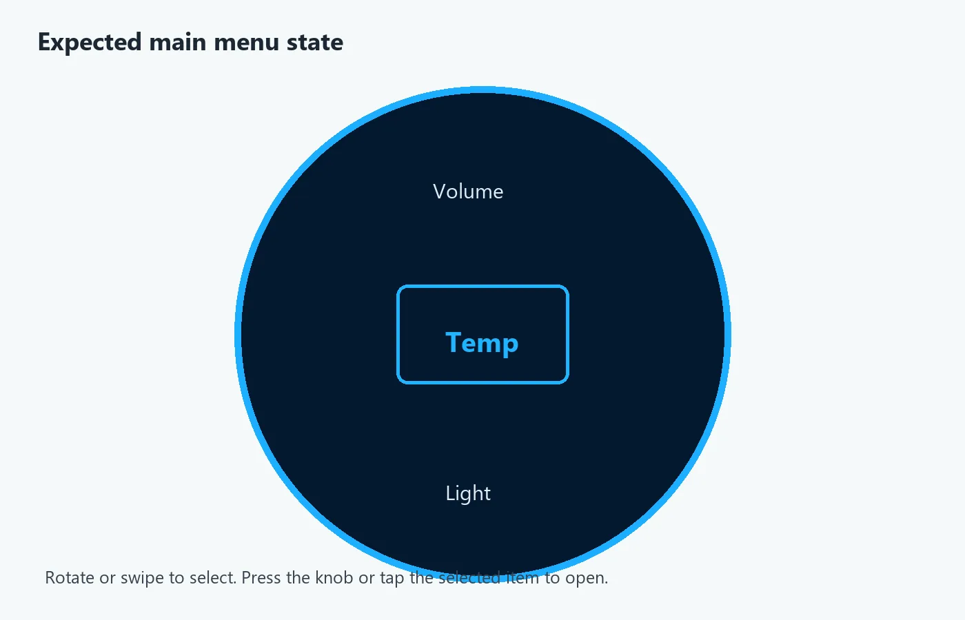
The expected main menu shows Volume, Temp, and Light, with the current item highlighted in the center.
Step03:
Confirm that you are using a 2.1-inch, 480 × 480 circular screen whose knob can rotate and be pressed.
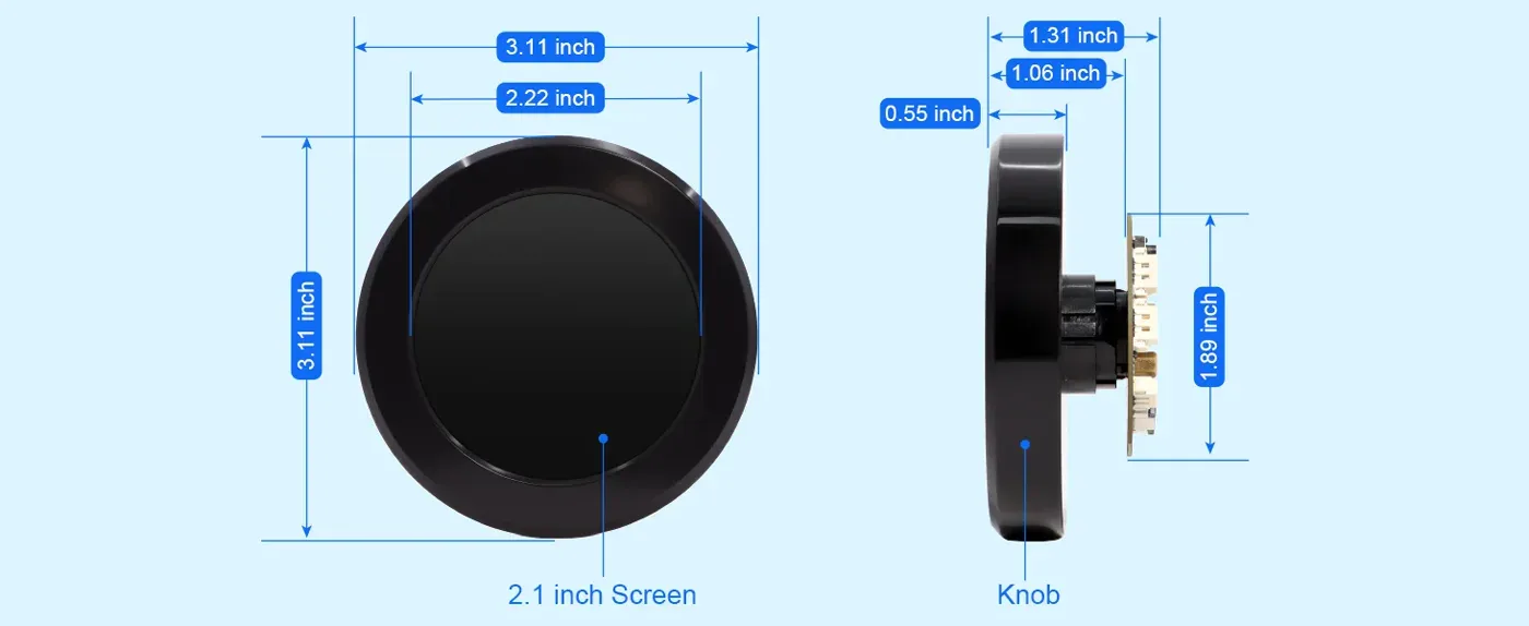
After flashing and resetting, observe the circular LCD display area; the images are used to illustrate the observation positions of the 2.1-inch screen. When this lesson actually runs, you should wait for the startup page to end and use the appearance of the Volume, Temp, and Light main menu as the acceptance criterion.
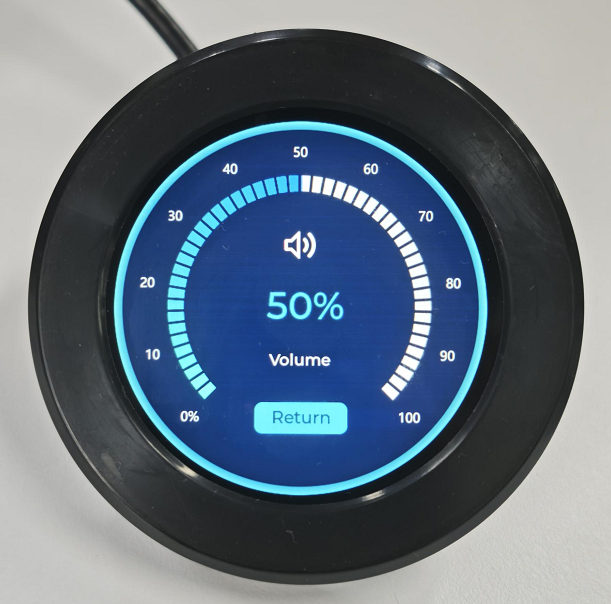
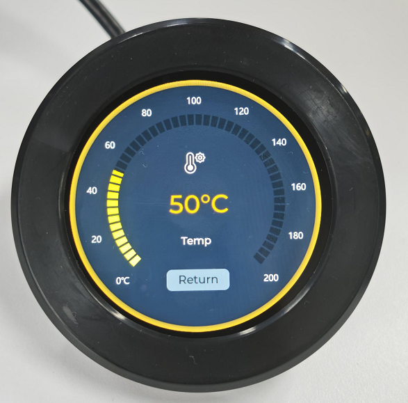
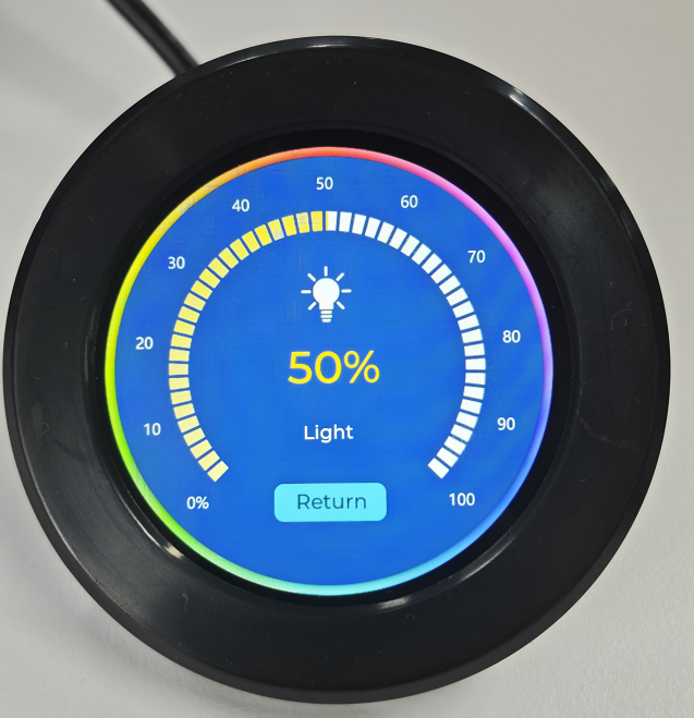
Step04:
On the detail page, rotate the knob or drag the arc with your finger to confirm that the value and the arc change in sync. Double-click the knob to return to the main menu. Do not touch the screen with sharp objects.
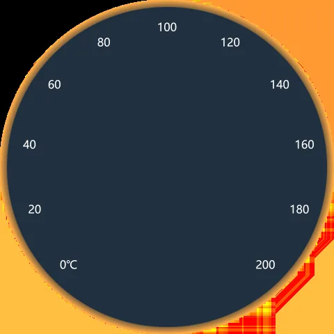
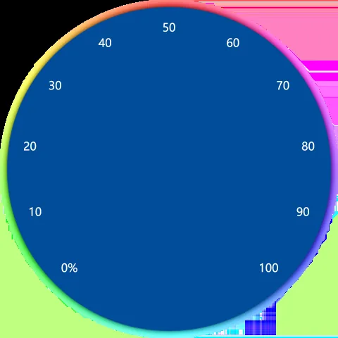
The following UI references show the temperature and volume arc layouts used by the detail pages.
6. Key Code Explanation
6.1 ST7701 RGB Display and PCF8574 Expansion I/O
#define I2C_SDA_PIN 38
#define I2C_SCL_PIN 39
PCF8574 pcf8574(0x21);

#define ENCODER_A_PIN 42
#define ENCODER_B_PIN 4
#define SCREEN_BACKLIGHT_PIN 6

Arduino_ESP32RGBPanel *rgbPanel = new Arduino_ESP32RGBPanel(
  40, 7, 15, 41,
  46, 3, 8, 18, 17,
  14, 13, 12, 11, 10, 9,
  5, 45, 48, 47, 21,
  1, 10, 4, 20,
  1, 10, 4, 20,
  0, 12000000, false,
  0, 0, 480 * 20);
The I2C bus on GPIO 38/39 connects to both the PCF8574 and the touch controller. The PCF8574's P0, P2, P3, P4, and P5 are used respectively for touch reset, touch interrupt, LCD power supply, LCD reset, and knob button. The encoder A/B phases use GPIO 42/4, and the backlight uses GPIO 6.
The RGB Panel parameters define the 16-bit data bus, sync signals, a 12 MHz pixel clock, and horizontal/vertical 10/4/20 timing. 480 * 20 is the DMA bounce buffer. They are bound to the PCB and the ST7701 panel; incorrect parameters will cause a black screen, scrolling, line misalignment, or flickering.
6.2 LVGL Screen Refresh, Color Conversion, and PSRAM Double Buffering
void my_disp_flush(lv_display_t *display,
                   const lv_area_t *area,
                   uint8_t *px_map) {
  uint32_t w = area->x2 - area->x1 + 1;
  uint32_t h = area->y2 - area->y1 + 1;
  uint16_t *pixels = (uint16_t *)px_map;

  for (uint32_t i = 0; i < w * h; ++i) {
    uint16_t c = pixels[i];
    pixels[i] = (c & 0x07E0) |
                ((c & 0x001F) << 11) |
                ((c & 0xF800) >> 11);
  }
  gfx->draw16bitRGBBitmap(area->x1, area->y1, pixels, w, h);
  lv_display_flush_ready(display);
}

size_t buffer_size = sizeof(uint16_t) * screenWidth * screenHeight;
buf1 = (uint8_t *)heap_caps_malloc(buffer_size, MALLOC_CAP_SPIRAM);
buf2 = (uint8_t *)heap_caps_malloc(buffer_size, MALLOC_CAP_SPIRAM);

lv_display_set_buffers(display, buf1, buf2, buffer_size,
                       LV_DISPLAY_RENDER_MODE_PARTIAL);
The flush callback processes only the region invalidated by LVGL this time and swaps the red and blue 5-bit fields in RGB565 to match the current display chain; lv_display_flush_ready() is used to notify LVGL that the current transfer has completed. When the color appears too red or too blue, you should first check here and the MADCTL 0x36 = 0x08 setting in the code.
A 480 × 480 RGB565 single buffer is 480 × 480 × 2 = 460800 bytes, and two buffers are about 900 KB, so they must be placed in OPI PSRAM. Although the buffers are allocated at full-screen size, the code uses PARTIAL mode, refreshing only the changed region to reduce bandwidth and screen tearing.
6.3 CST8XX Touch, Coordinate Stabilization, and Swipe Recognition
#define I2C_TOUCH_ADDR 0x15

const int SWIPE_THRESHOLD = 100;
const int TIME_THRESHOLD = 300;
const int VERTICAL_LIMIT = 100;

const int16_t touchX = constrain(p.x, 0, screenWidth - 1);
const int16_t touchY = constrain(p.y - 20, 0, screenHeight - 1);
if (stableX < 0 || abs(touchX - stableX) >= 4 ||
    abs(touchY - stableY) >= 4) {
  stableX = touchX;
  stableY = touchY;
}
The touch controller is located at address 0x15. The Y coordinate is reduced by 20 before being constrained to 0–479, compensating for the offset between the touch panel and the visible area; when the coordinate change is less than 4 pixels, the stable value is retained to reduce jitter while the finger remains still.
The main menu swipe requires a horizontal displacement greater than 100 pixels within 300 ms, while the vertical offset is less than 100 pixels. swipeHandled ensures that a single touch switches only one menu position.
6.4 Initialization Order, UI Loading, and Startup Animation
Wire.begin(I2C_SDA_PIN, I2C_SCL_PIN);
pcf8574.begin();
pcf8574.digitalWrite(P3, HIGH);

gfx->begin();
tsPanel.begin(&Wire, I2C_TOUCH_ADDR);

lv_init();
lv_tick_set_cb(millis);
ui_init();

lv_obj_add_event_cb(ui_VolumeArc, volumeArcEventCb,
                    LV_EVENT_VALUE_CHANGED, NULL);
lv_obj_add_event_cb(ui_TempArc, tempArcEventCb,
                    LV_EVENT_VALUE_CHANGED, NULL);
lv_obj_add_event_cb(ui_lightArc, lightArcEventCb,
                    LV_EVENT_VALUE_CHANGED, NULL);
The program first starts I2C and PCF8574, completing the LCD/touch power supply and reset, then initializes the display, touch, LVGL, and UI. ui_init() creates Screen0 through Screen4; once the rotation animation of Screen0 completes, its ready callback fades in Screen1, the main menu. The value-change callbacks are then bound to the three arcs.
If the interface is stuck on the startup page, you should check whether progress_Animation_ready_cb() has been overwritten by a SquareLine re-export, and whether loop() continuously calls lv_timer_handler().
6.5 Display and Hardware Output of the Three Arcs
void volumeArcEventCb(lv_event_t *e) {
  int value = lv_arc_get_value((lv_obj_t *)lv_event_get_target(e));
  volumeValue = value;
  ledcWrite(BREATH_LED_PIN, (value * 255) / 100);
}

void tempArcEventCb(lv_event_t *e) {
  int value = lv_arc_get_value((lv_obj_t *)lv_event_get_target(e));
  snprintf(tempText, sizeof(tempText), " %d°C", value);
  lv_label_set_text(ui_TempNum, tempText);
}

void lightArcEventCb(lv_event_t *e) {
  int value = constrain(lv_arc_get_value(
                        lv_event_get_target_obj(e)), 0, 100);
  ledcWrite(SCREEN_BACKLIGHT_PIN, (value * 255) / 100);
}
Volume: range 0–100, adjusts the PWM of the indicator LED on GPIO 43; not an audio volume control.Temp: range 0–200, only updates the°Clabel; does not read a temperature sensor.Light: range 0–100, maps the percentage to a 0–255 PWM on GPIO 6, directly controlling the screen backlight.
6.6 Encoder Task, Event Queue, and Button Recognition
encoderActionQueue = xQueueCreate(16, sizeof(EncoderAction));
xTaskCreatePinnedToCore(encTaskSafe, "ENC", 2048,
                        NULL, 1, &encTaskHandle, 0);

void encTaskSafe(void *pvParameters) {
  int previousA = digitalRead(ENCODER_A_PIN);
  while (true) {
    const int currentAState = digitalRead(ENCODER_A_PIN);
    if (currentAState != previousA && currentAState == HIGH) {
      EncoderAction action;
      action.type = (digitalRead(ENCODER_B_PIN) != currentAState)
                      ? ENCODER_ROTATE_CCW : ENCODER_ROTATE_CW;
      xQueueSend(encoderActionQueue, &action, 0);
    }
    previousA = currentAState;
    vTaskDelay(pdMS_TO_TICKS(2));
  }
}
The encoder task is pinned to Core 0, reading the A/B phases every 2 ms and writing actions into a queue of length 16. The background task does not call LVGL directly; the Arduino main loop retrieves the actions before updating the UI, avoiding cross-core simultaneous modification of non-thread-safe LVGL objects.
The knob button is read via PCF8574 P5, and state changes are only accepted at intervals of at least 50 ms. The first press waits 300 ms: a second press within this window counts as a double-click, otherwise it is a single-click.
6.7 Page Navigation and Knob Adjustment
void handleEncoderAction(EncoderActionType type) {
  if (type == ENCODER_CLICK) {
    performClickAction();
    return;
  }
  if (type == ENCODER_DOUBLE_CLICK) {
    performDoubleClickAction();
    return;
  }

  const int delta = (type == ENCODER_ROTATE_CW) ? 5 : -5;
  current_screen = lv_screen_active();
  if (current_screen == ui_Screen2 && ui_VolumeArc) {
    int value = constrain(lv_arc_get_value(ui_VolumeArc) + delta, 0, 100);
    lv_arc_set_value(ui_VolumeArc, value);
    lv_obj_send_event(ui_VolumeArc, LV_EVENT_VALUE_CHANGED, NULL);
  } else if (current_screen == ui_Screen3 && ui_TempArc) {
    int value = constrain(lv_arc_get_value(ui_TempArc) + delta, 0, 200);
    lv_arc_set_value(ui_TempArc, value);
    lv_obj_send_event(ui_TempArc, LV_EVENT_VALUE_CHANGED, NULL);
  }
}
The main menu index is limited to 0–2, corresponding respectively to Volume, Temp, and Light. A single-click enters the current detail page, and a double-click returns from the detail page to the main menu. The rotation step on the detail page is 5; after setting the arc, it proactively sends LV_EVENT_VALUE_CHANGED so that the label and PWM stay in sync with the knob.
The main loop continuously processes the button, the queue, and LVGL:
void loop() {
  pollEncoderButton();
  EncoderAction action;
  while (encoderActionQueue &&
         xQueueReceive(encoderActionQueue, &action, 0) == pdTRUE) {
    handleEncoderAction(action.type);
  }
  lv_timer_handler();
  delay(5);
}
lv_timer_handler() is responsible for animations, touch, events, and redraws. Removing it will stop the interface from responding; significantly increasing the delay will cause noticeable lag.
6.8 Libraries Actually Called by the Main Code
| Library | Header in main code | Purpose in this lesson |
|---|---|---|
| LVGL 9.1.0 | lvgl.h | Page objects, animations, input events, and refresh scheduling |
| GFX Library for Arduino | Arduino_GFX_Library.h | ST7701 initialization, ESP32 RGB Panel, and pixel transfer |
| Adafruit CST8XX | Adafruit_CST8XX.h | Reading touch points and coordinates |
| PCF8574 | PCF8574.h | Controlling LCD/touch reset, LCD power supply, and reading the knob button |
| UI | ui.h | Five SquareLine-generated pages, objects, and image resources |
| ESP32 Arduino Core | esp_system.h | Obtaining the reset reason and low-level ESP32 functions |
Adafruit_BusIO is the communication dependency of CST8XX.
7. Experimental Observations
7.1 Power-On and Startup
- After reset, the serial port outputs the ESP32 Arduino, LVGL version, and reset reason.
- On PCF8574 success it outputs
pcf8574 OK; on touch success it outputsTouchscreen found. - The screen clears to black first, then displays the startup page and rotation animation.
- After the animation ends, the main menu fades in, and
Settings completed.is output.
[BOOT] ESP32 Arduino 3.3.8, LVGL 9.1.0, reset_reason=1
Init pcf8574...
pcf8574 OK
Touchscreen found
Settings completed.
The reset reason number changes with power-on, button reset, or software reset, and is not used as a basis for failure.
7.2 Main Menu and Knob
- The main menu displays
Volume,Temp, andLight, with the middleTempinitially selected. - When sliding left/right quickly or rotating the knob, the selected item moves between the three indexes without crossing the first or last.
- After the knob moves, the serial port outputs something like
cur_index: 0,cur_index: 1, orcur_index: 2. - Touching the blue selected item or single-clicking the knob fades the interface into the detail page in about 200 ms.
7.3 Three Detail Pages
Volume: initial value 50%, range 0–100; the knob changes 5 per notch; the brightness of the indicator LED on GPIO 43 changes synchronously, with no sound played.Temp: initial value 50°C, range 0–200; the value exists only in the interface and does not represent an actual measured temperature.Light: initial value 50%, range 0–100; the GPIO 6 backlight changes synchronously. At 0%, the screen may become completely invisible.- Touch
Return, or double-click the knob on the detail page, to return the interface to the main menu.
7.4 Display, Touch, and Stability
The 480 × 480 image should fully cover the circular visible area, with normal colors and no persistent screen corruption, line misalignment, or obvious tearing. When continuously operating touch, knob, and page switching, the device should not repeatedly reset, get stuck for a long time, or stop responding.
7.5 Common Issue Checks
- Insufficient firmware space: confirm that Flash Size is 16 MB and Partition Scheme is
elecrow_s3; do not choose 3 MB Huge APP. lvgl.h,ui.h, or other header files missing: confirm the complete library directory has been copied, and check the library path actually used in the compilation log.Failed to allocate for LVGL: confirm that Board is ESP32S3 Dev Module and PSRAM is OPI PSRAM.- Black screen: first confirm
pcf8574 OK, then check whether Light is 0%, the RGB timing, and the GPIO 6 backlight. - Red/blue swapped: check the R/B bit-field swap in the flush callback and
MADCTL 0x08; do not modify the UI image first. - No touch: confirm address
0x15, I2C GPIO 38/39, the PCF8574 P0/P2 timing, and the LVGL input callback. - Knob false triggers: keep the 50 ms debounce and 300 ms double-click window, and check GPIO 42/4 and PCF8574 P5.
- Startup page does not switch: check the animation ready callback and
lv_timer_handler().