2.4_2.8inch_Lesson05_I2C_and_DHT20_Display
1. Course Introduction
This lesson brings together the I2C interface, the DHT20 temperature and humidity sensor, touch input, and the LVGL interface. The program periodically reads temperature and humidity and updates the values on screen labels, allowing learners to see how sensor data drives the UI.
Reference materials:
2. Learning Objectives
- Be able to distinguish which peripherals are handled by
WireandWire1respectively. - Be able to complete DHT20 sensor initialization and read temperature and humidity.
- Be able to write sensor data into LVGL labels and observe the on-screen changes.
3. What You Need
- CrowPanel Advance 2.4inch development board.
- A USB data cable that supports data transfer.
- DHT20 temperature and humidity sensor.
- The LVGL UI file and image assets included in the project.
- Project:
Port_CrowPanel_ESP32_Advance_HMI_2.4_2_8.ino
Code and Resource Download
Code download: - Port_CrowPanel_ESP32_Advance_HMI_2.4_2_8
Resource download:
4. Software Operation Steps
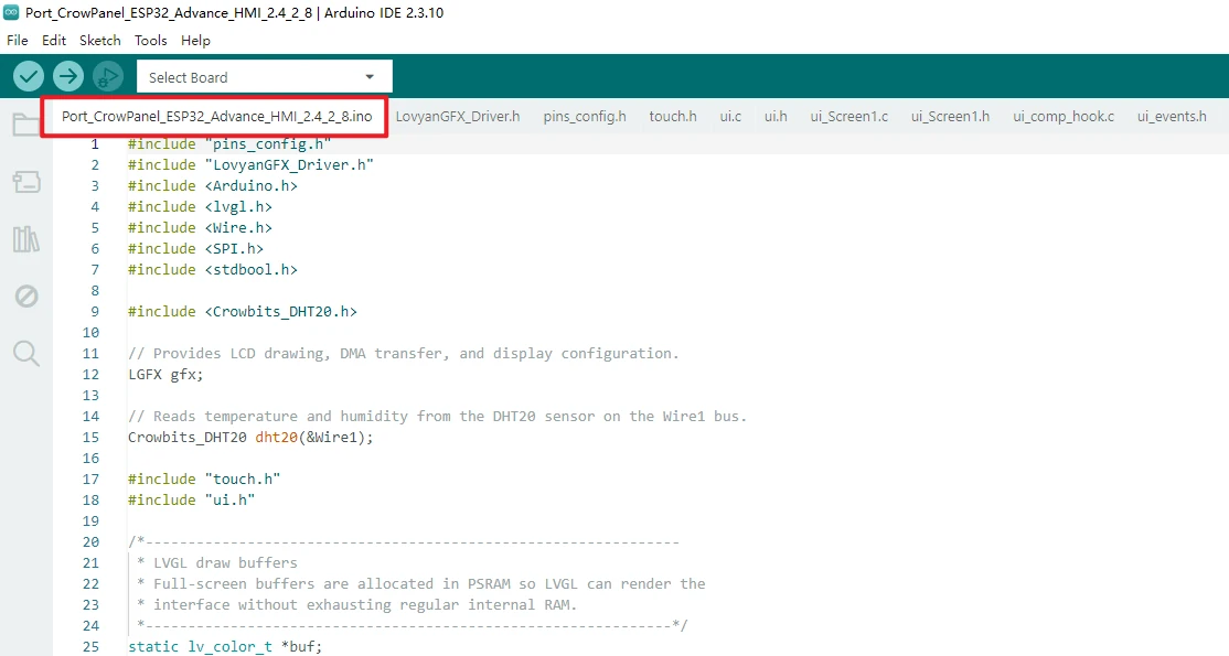
Open this lesson's project in Arduino IDE: Port_CrowPanel_ESP32_Advance_HMI_2.4_2_8.ino
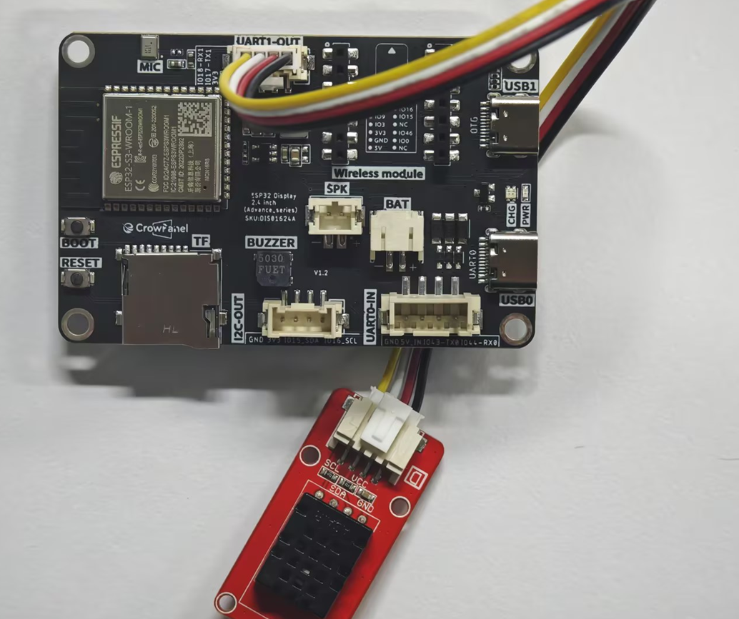
Connect the DHT20 to the UART1-OUT interface, and use a USB cable that supports data transfer to connect the development board to the computer.
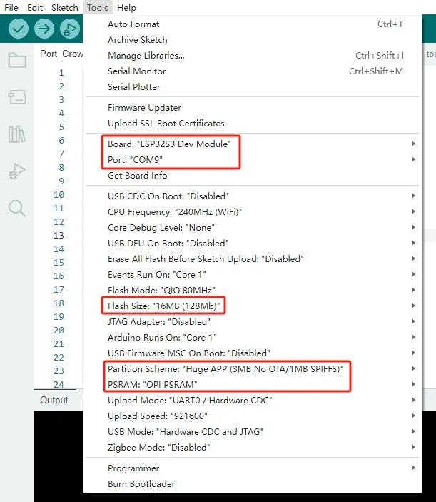
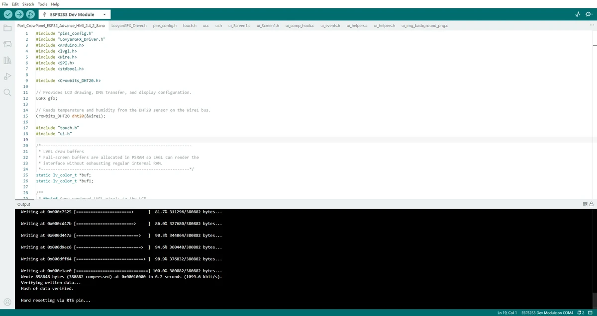
In the Tools menu, complete the development environment configuration in order: set Board to ESP32S3 Dev Module, select the serial port corresponding to the development board under Port, set Flash Size to 16MB (128Mb), set PSRAM to OPI PSRAM, and set Partition Scheme to Huge APP (3MB No OTA/1MB SPIFFS). After completing the above configuration, you can compile and upload the program.
Note: If the Arduino IDE reports a compilation error, go back to Lesson 01 first and check whether the ESP32 Core, board model, PSRAM, Flash Size, and course library files are consistent.
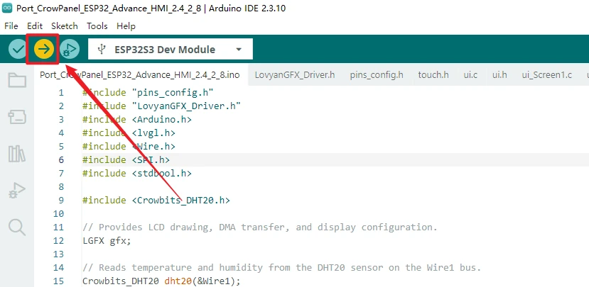
Click Upload to compile and upload the code.
5. Hardware Operation Steps
The on-board touch chip on the 2.4-inch and 2.8-inch versions has an IIC address of 0x38, and the DHT20 default IIC address is also 0x38. If the DHT20 is connected directly to IIC-OUT, an address conflict will occur. Therefore, this lesson reconfigures IO17 and IO18 on UART1-OUT as I2C to connect the DHT20 temperature and humidity sensor.
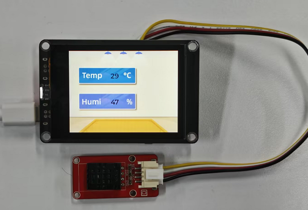
Connect the DHT20 to the UART1-OUT interface, with IO17 as SDA and IO18 as SCL, and also connect power and GND.
After flashing is complete, observe the screen display; the temperature and humidity values should keep refreshing continuously.
6. Key Code Explanation
Wire is responsible for on-board peripherals such as the touch controller, using GPIO15 and GPIO16; Wire1 uses GPIO17 and GPIO18 on the UART1-OUT interface and is reserved specifically for the DHT20. This avoids the IIC address conflict where both the touch chip and the DHT20 share the address 0x38.
These two lines actually write the values into the interface. If the sensor readings are normal but the screen does not change, first check whether the UI object names are consistent, whether ui_init() has been called, and whether the label objects have been regenerated.
7. UI Asset Creation Process
Next, we will explain using the example of connecting a temperature and humidity sensor externally to the UART1-OUT interface. To make the experimental result more intuitive, this lesson uses LVGL to create an interface that displays temperature and humidity.
For SquareLine Studio download and installation instructions, refer to: https://www.elecrow.com/wiki/Create_LVGL_UI_with_SquareLine_Studio.html
Open SquareLine Studio.
After launching SquareLine Studio, enter the main interface. If the software is not yet installed, refer to Lesson 03 or the link above to complete the installation first. This lesson uses it to generate the LVGL ui.c, ui.h, image assets, and widget object files.
Create an Arduino project template.
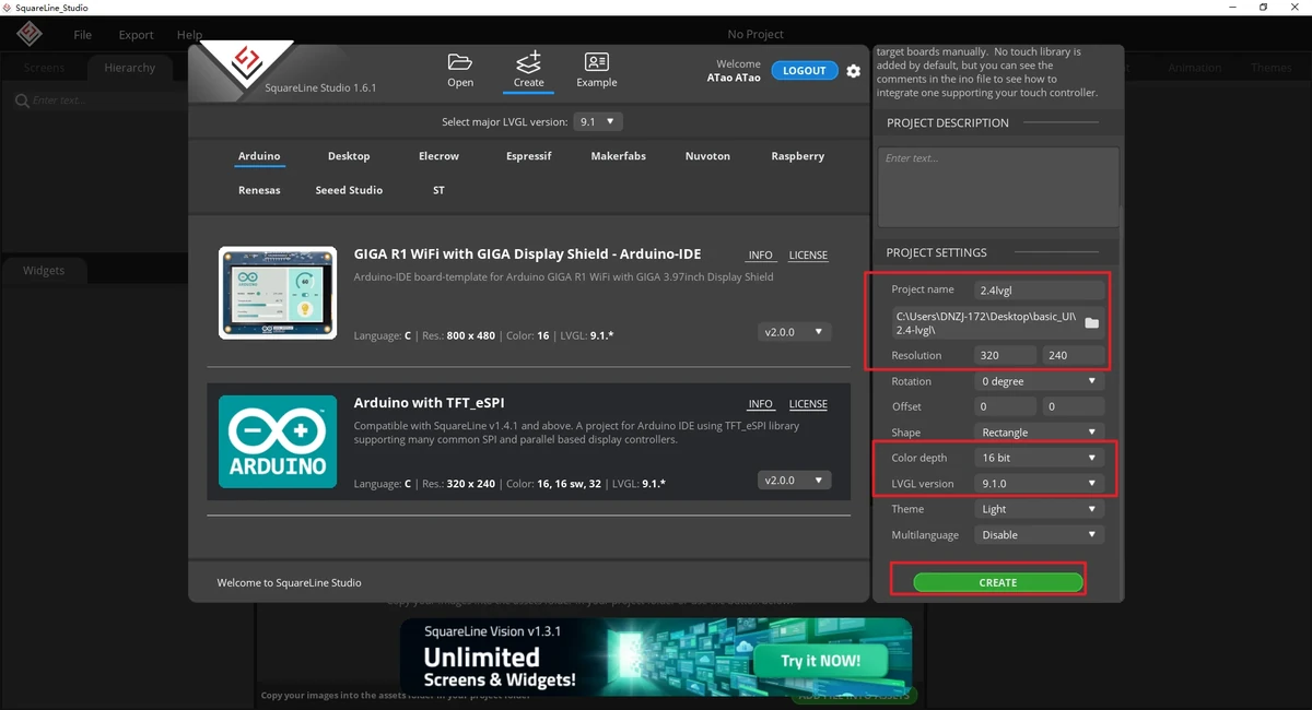
On the welcome screen, first click Create at the top. When creating a new project, you must select LVGL 9.1.0. Then select Arduino from the category list on the left, and choose the Arduino with TFT_eSPI template in the middle. This template generates a UI file framework suitable for Arduino projects.
Note: When selecting the Arduino framework, SquareLine Studio only displays the Arduino with TFT_eSPI option. It generates template code suitable for TFT_eSPI, but SquareLine Studio also supports other graphics libraries; when switching to other hardware, you need to modify the display code according to the actual library.
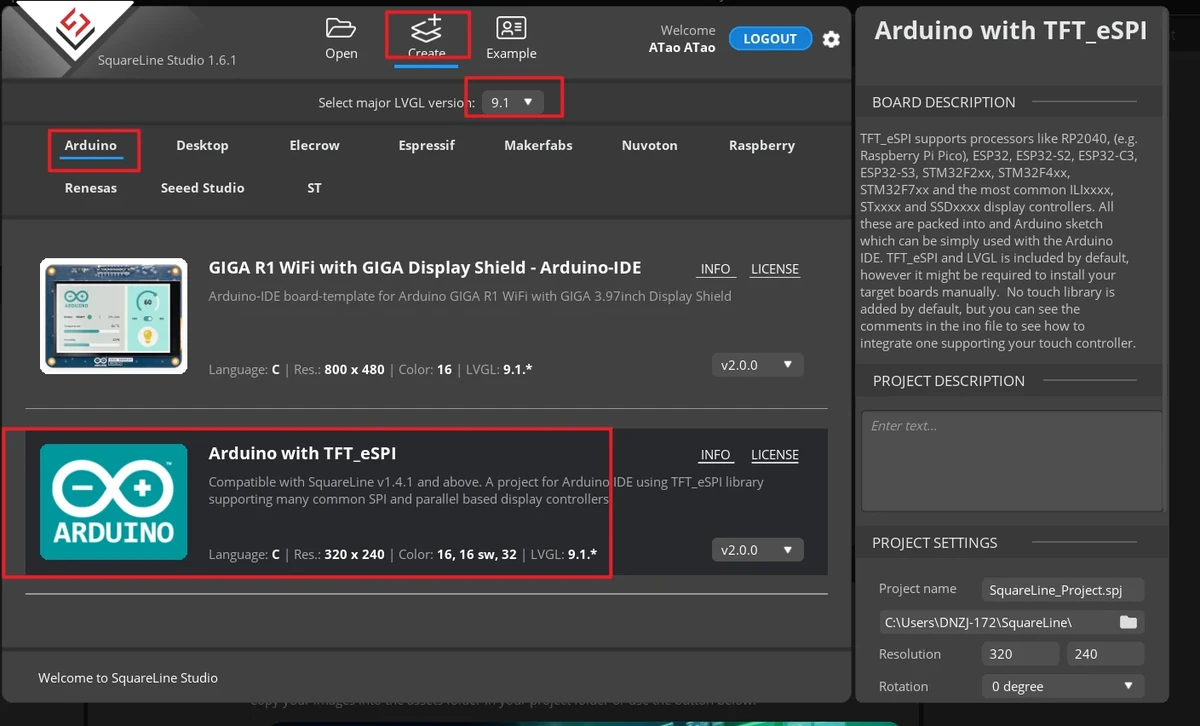
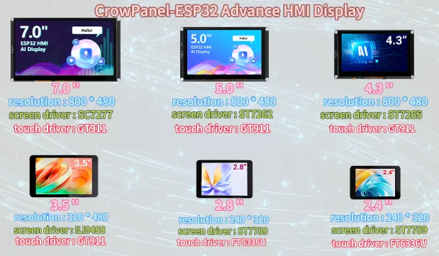
Confirm the resolution based on the screen size. The 2.4-inch and 2.8-inch course projects use 320 x 240.
In Project Settings on the right, set the project name and path, and confirm the key parameters:
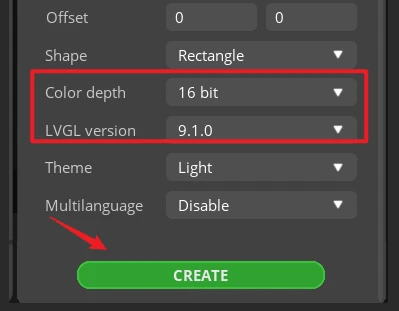
After confirming the parameters, click CREATE to create the project.
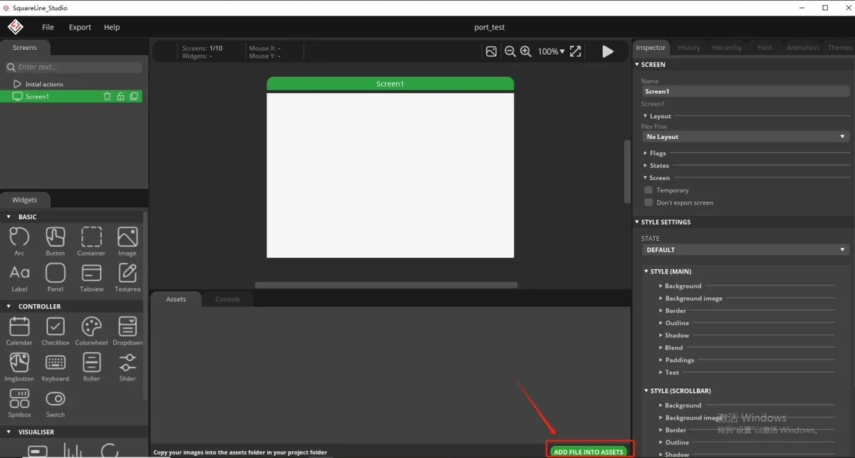
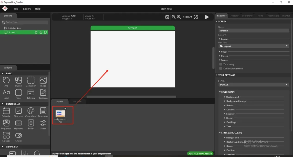
Prepare the background image assets provided by the course.
This lesson's interface requires the background image provided by the course. Different screen sizes require corresponding resolution assets; the 2.4-inch and 2.8-inch products can use the images in the 320x240 folder. Add the image to the assets of the SquareLine Studio project so it can be selected on the canvas later.
Image asset download link: 320x240 assets
Asset links:
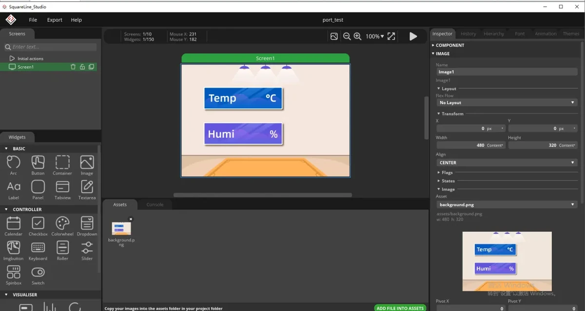
Place the background image onto the interface canvas.
In the widgets or assets area on the left, select the image widget and add the background image to the current Screen. After adding, select the just-imported background image in the properties panel on the right, and adjust its position and size so it fills the entire 320*240 canvas.
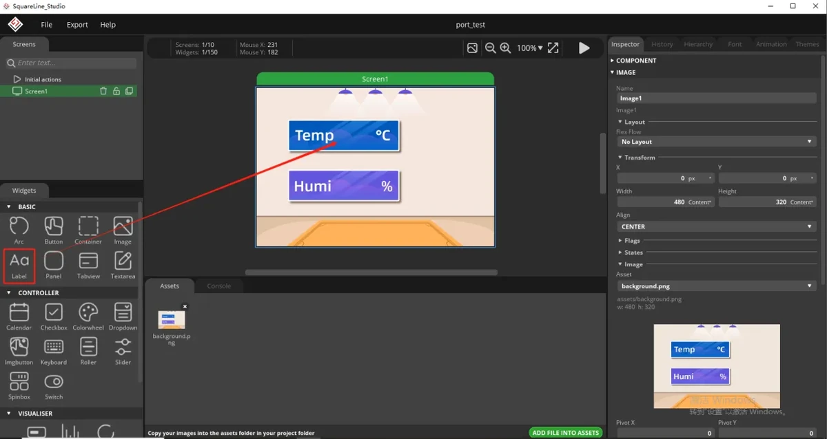
Add a text label for the temperature value.
Since the temperature value needs to be displayed on the screen, add a text label in the temperature display area. After selecting the Text or Label widget, drag it into the temperature box so the value appears at the position reserved on the background image.
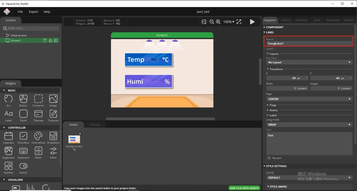
Set the object name for the temperature label.
In the properties panel on the right, modify the label's name. It is recommended to keep it consistent with the object name in the code, for example TempLabel1. The Arduino program will later find this label through the exported object name and write the temperature value read by the DHT20 into it.
Fill in the default display value for the temperature label.
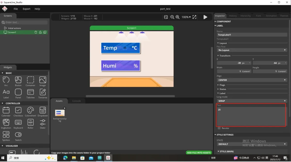
In the label text content, fill in a default temperature value, for example 25. This value is only placeholder content during the UI design phase and will be replaced by the real-time temperature value read from the sensor after the program runs.
Set the font style for the temperature label.
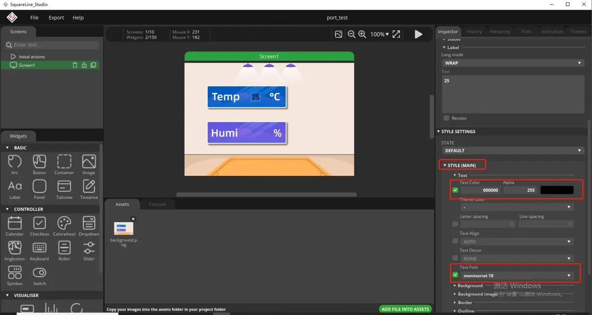
Set the label font color and size according to the background image color. To make the numbers clearly visible on the screen, you can set the font color to white and choose an appropriate font size, for example using larger digits to display the temperature value as shown in the screenshot.
Duplicate the temperature label as the humidity label.
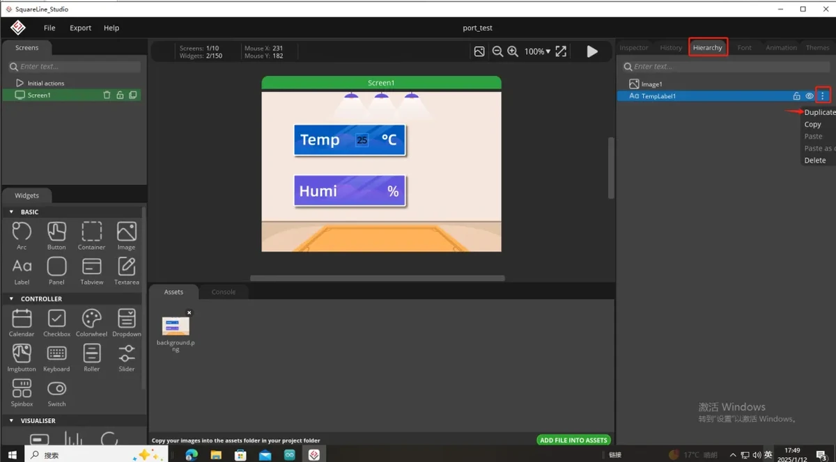
The display styles for temperature and humidity are basically the same, so you can duplicate the temperature label you just created and move the duplicated label to the humidity display area. This keeps the font size, color, and alignment consistent for both values.
Modify the humidity label name and default value.
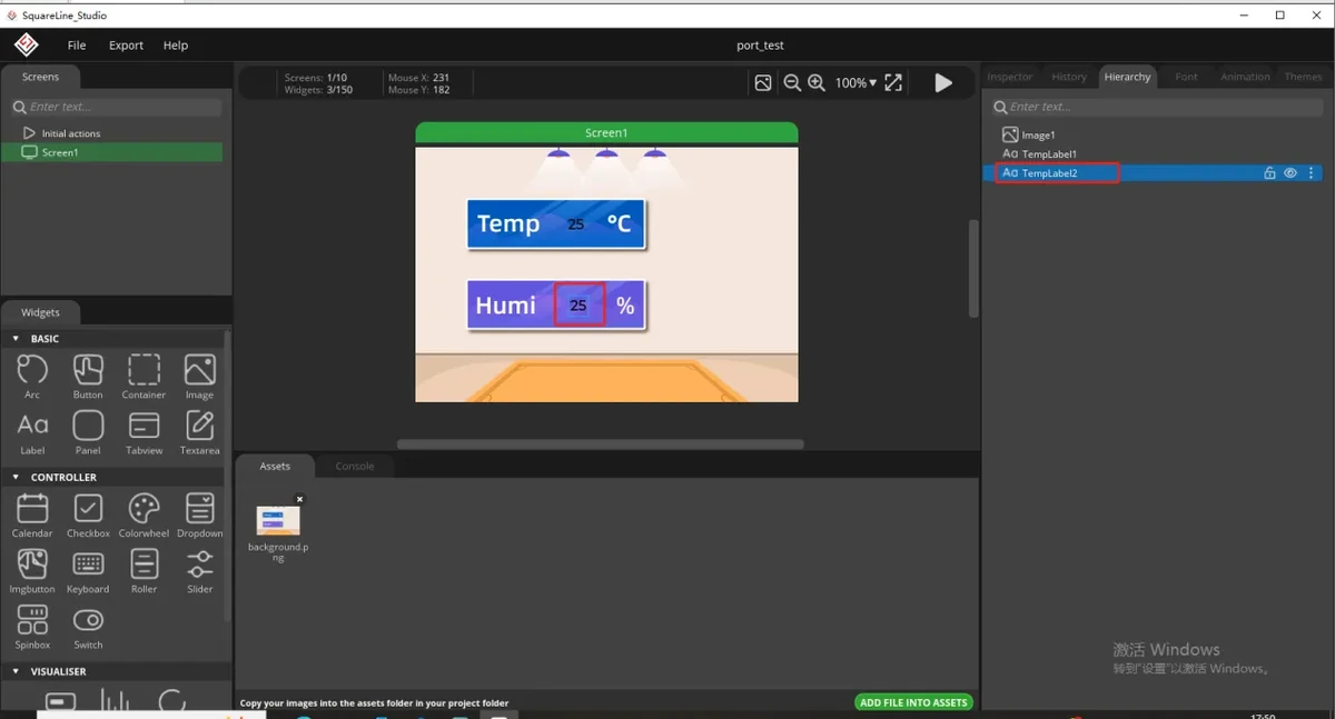
Select the duplicated label, and in the properties panel on the right change the name to the humidity label object name, for example HumiLabel2; then change the default text to a sample humidity value, for example 50. The code will update the humidity display through this object name.
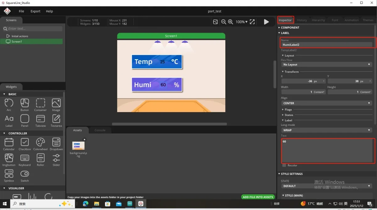
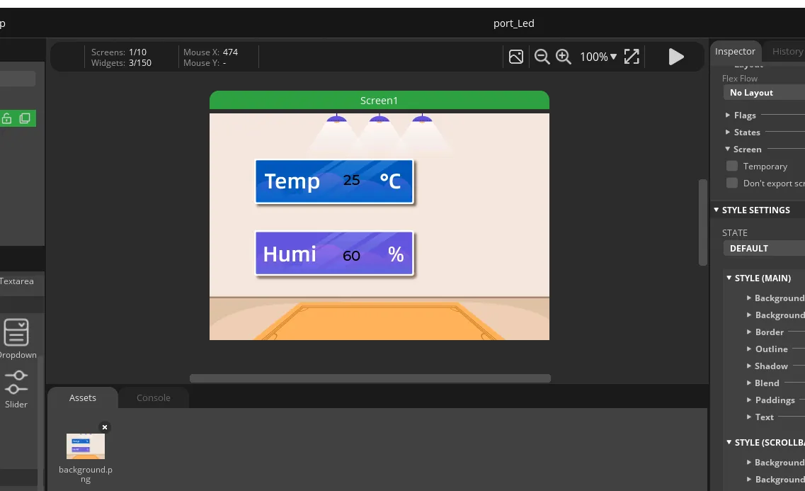
Check the overall UI effect.
After the background image, temperature label, and humidity label are all set, check whether the two values are located in their respective areas, whether the font is clear, and whether there is any offset or occlusion. Once the effect is confirmed correct, the UI interface needed for this lesson is complete.
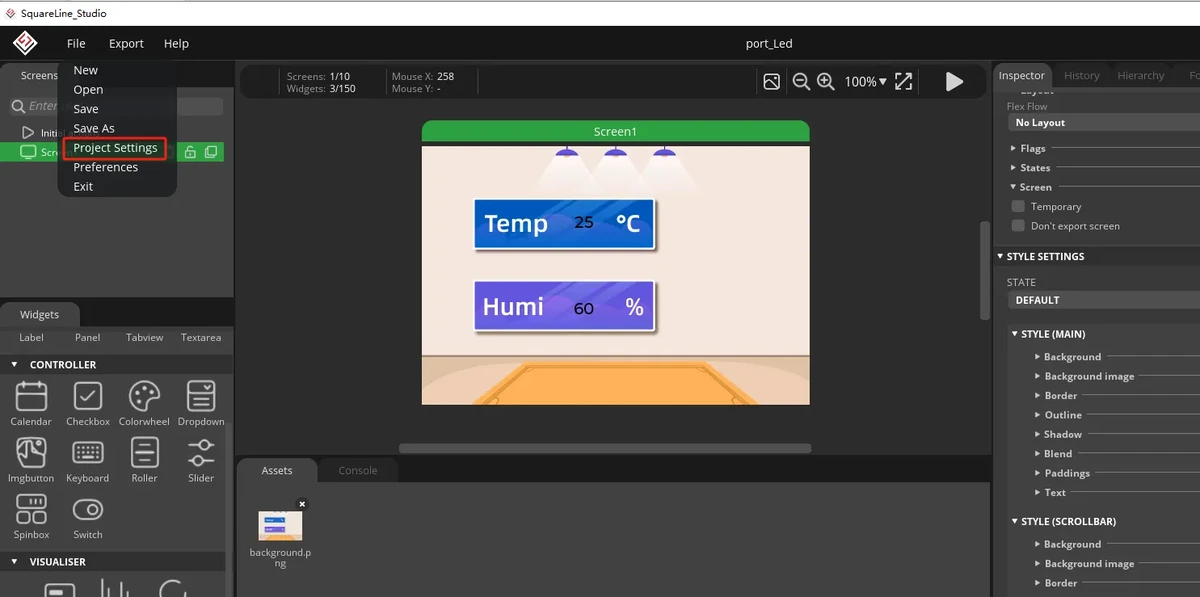
Open the project export settings.
Click Project Setting in SquareLine Studio to enter the project export configuration page. The export settings determine where the generated UI files are placed and which LVGL header file is included in the code.
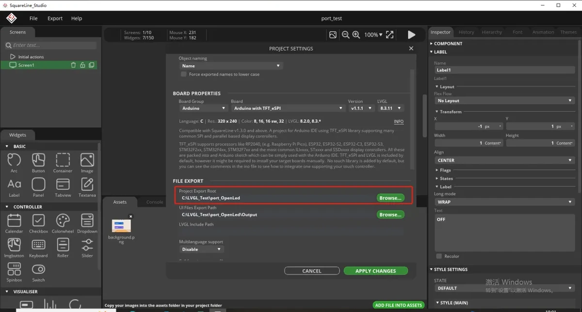
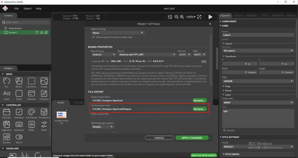
Set the UI file export path.
In the export path, select the directory used when creating the project earlier, or define a dedicated location to save the exported files. It is recommended to avoid an overly deep directory hierarchy to make copying files easier later.
Create an Output folder to receive the exported files.
Under the path you just set, create a new Output folder. The ui.c, ui.h, ui_helpers.*, image .c files, and others exported by SquareLine Studio will all be placed in this folder.
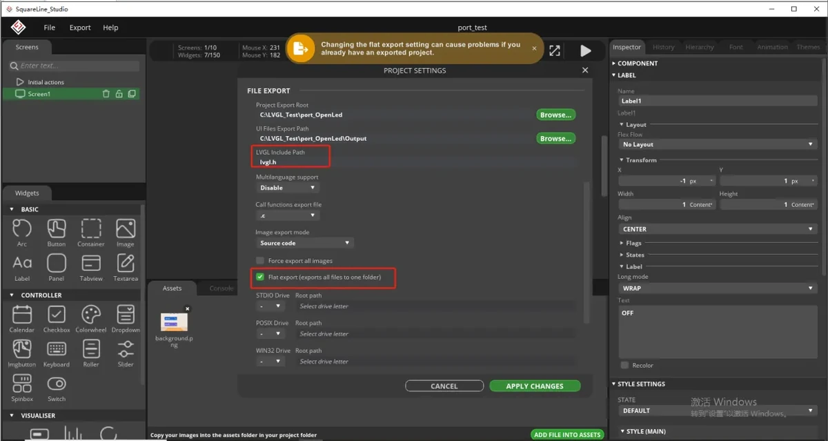
Set the LVGL header file and export method.
In the project settings, fill in LVGL include as lvgl.h and select Flat export. Flat export places the exported UI files in the same directory level, making them easier to copy into the project.
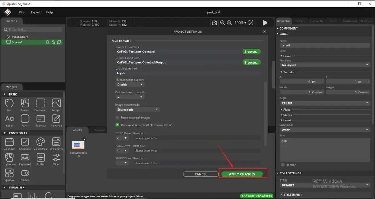
Confirm the export settings.
After checking that the export path, lvgl.h, and Flat export are all set correctly, click the confirm button to save the project settings.
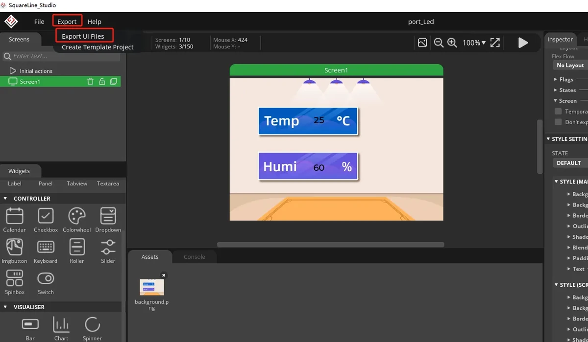
Export the UI files.
After returning to the main interface, perform the export operation to generate the UI interface files designed in this lesson. After the export is complete, go to the Output folder to view the generated results.
Copy the generated UI files.
Open the Output folder you just created and select the exported UI-related files. Typically you need to copy ui.c, ui.h, ui_helpers.c, ui_helpers.h, the interface files, the image asset .c files, and so on.
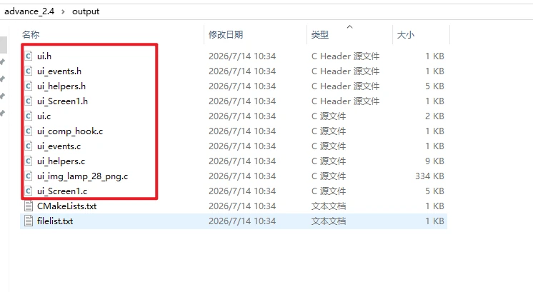
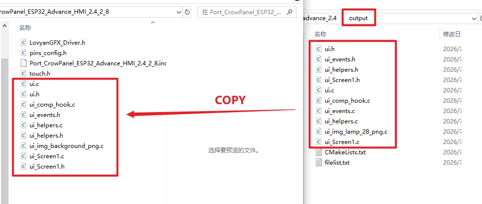
Paste into this lesson's Arduino project directory.
Paste the copied UI files into this lesson's code project directory, overwriting or replacing the original UI files. The project directory used in this course is Port_CrowPanel_ESP32_Advance_HMI_2.4_2_8; use this course directory as the reference when operating.
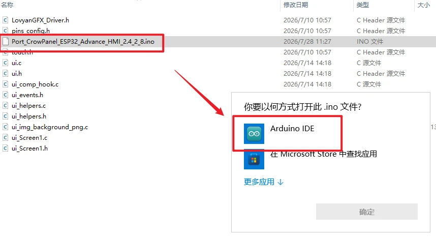
Open the project in Arduino IDE.
Finally, use Arduino IDE to open the Port_CrowPanel_ESP32_Advance_HMI_2.4_2_8.ino file in the project directory. Once opened, you can follow the software operation steps above to select the board, port, and upload the program.
8. Experimental Results
Observe the screen display; the temperature and humidity values should keep refreshing continuously.
9. Code Download
- Code download link: Port_CrowPanel_ESP32_Advance_HMI_2.4_2_8
- Image asset download link: source material