3.5inch_Lesson01_Serial_Counter
1. Course Introduction
This lesson uses the Elecrow CrowPanel Advance 3.5inch ESP32-S3 development board to complete board environment configuration, project opening, compilation, flashing, and serial monitoring in the Arduino IDE. The program does not initialize the LCD, touchscreen, or other peripherals; it only outputs Hello, World! and an incrementing counter value over the USB debug serial port approximately once every second, used to verify the basic chain of "computer, USB data cable, development board, firmware program, serial monitor."
2. Learning Objectives
- Be able to perform ESP32-S3 board environment checks and basic parameter settings in the Arduino IDE.
- Be able to open the 3.5inch Lesson01 project and complete compilation and flashing.
- Be able to set the
9600baud rate and see incrementing output in the serial monitor. - Be able to troubleshoot USB, port, baud rate, and board configuration issues based on symptoms such as garbled output, no output, upload failure, or non-incrementing counter.
3. Preparation
- Hardware: CrowPanel Advance 3.5inch ESP32-S3 development board.
- Cable: A USB data cable that supports data transfer.
- Software: Arduino IDE, ESP32 Arduino development environment. Install Arduino IDE .
- Board package:
esp32 by Espressif Systems3.3.8. - Project:
Serial_port_printing.ino.
Code and Resource Download
Code download: - lesson-01/Serial_port_printing
4. Software Operation Steps
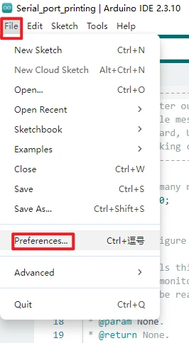
Open the Arduino IDE and go to File > Preferences. The Arduino IDE version is not strictly required, but version 2.x is recommended so that the interface matches this tutorial.
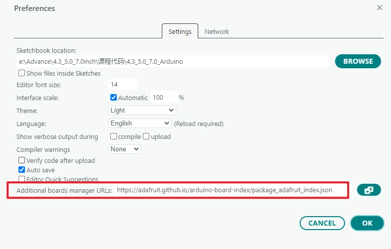
In Additional boards manager URLs, add the Espressif ESP32 board index URL:
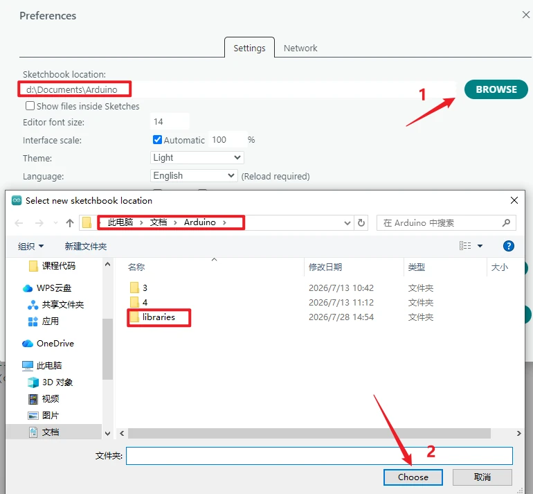
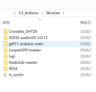
Import the Arduino library files: Before running the example program, first import the Arduino library files required by the project. Go to File → Preferences, check the Sketchbook location, and open the libraries folder under that path.
Link to the two ways of importing Arduino IDE third-party libraries: https://www.elecrow.com/wiki/Arduino_IDE_Library_Import_Guide.html
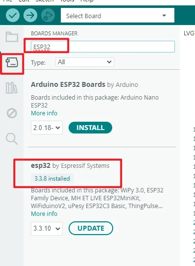
Open Tools > Board > Boards Manager, search for esp32, and confirm that esp32 by Espressif Systems is installed. Version 3.3.8 is recommended; if the release environment standardizes on another version, follow the release notes.
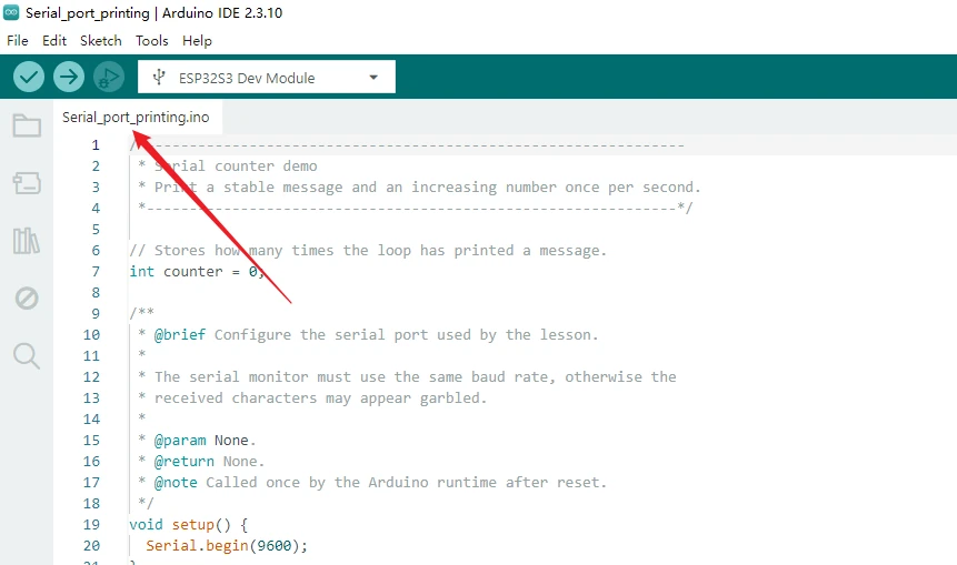
Open Serial_port_printing.ino with the Arduino IDE.
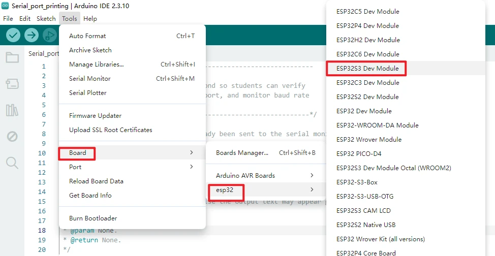
Under Tools > Board > esp32, select ESP32S3 Dev Module.
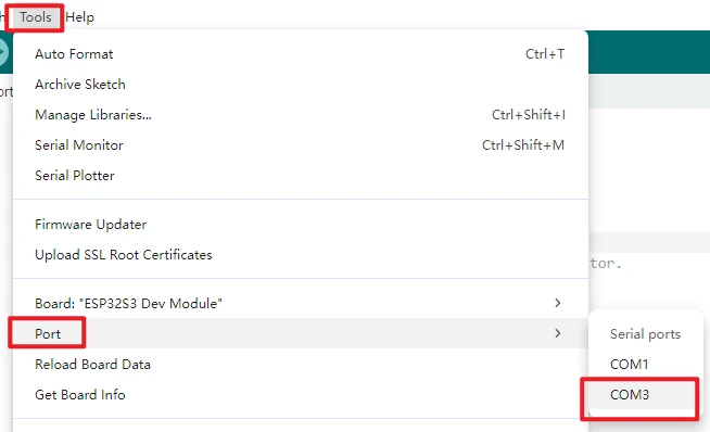
After connecting the board, select the newly appeared device serial port under Tools > Port.
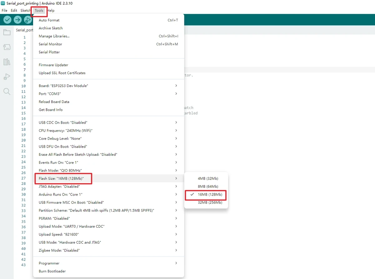
Set Flash Size to 16MB (128Mb).
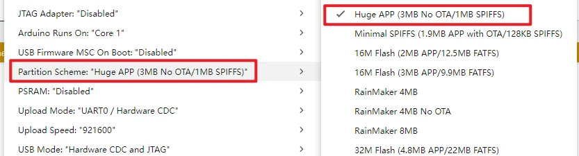
Set Partition Scheme to Huge APP (3MB No OTA/1MB SPIFFS)
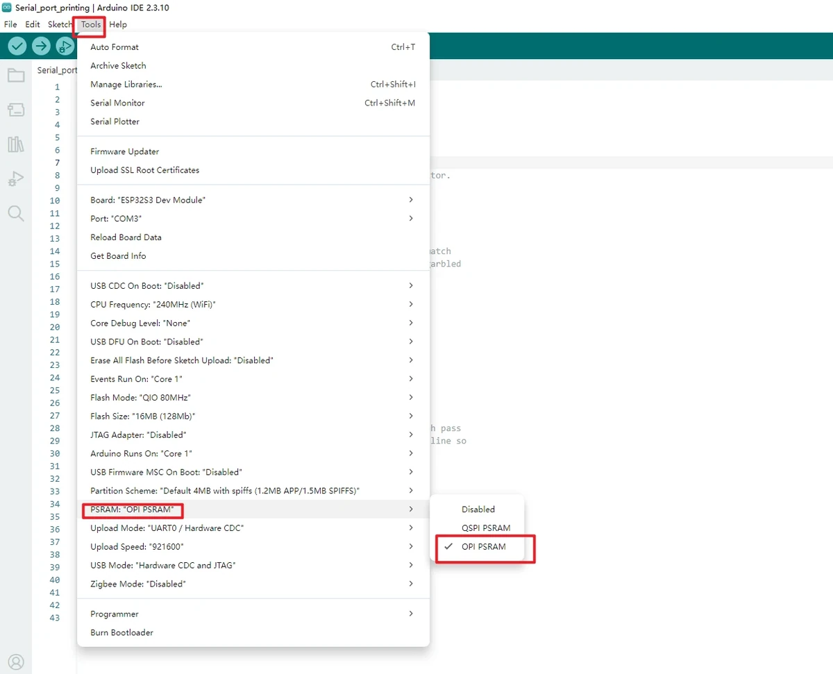
Set PSRAM to OPI PSRAM.
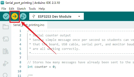
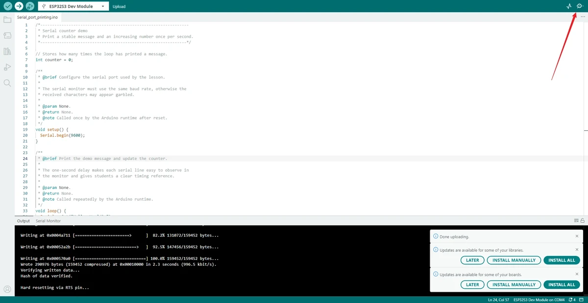
Click Upload to compile and wait for the upload to finish. If it gets stuck at Connecting..., check for port conflicts and use the BOOT/RESET download mode as required by the board.
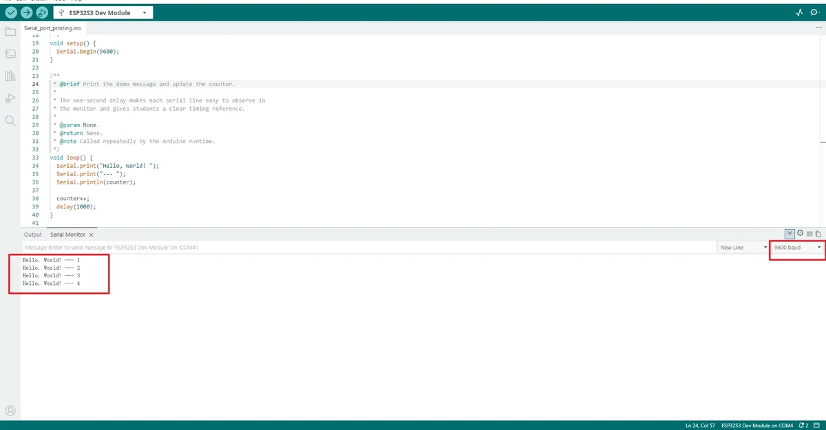
Open the Serial Monitor in the top-right corner, set it to 9600 baud, and observe the continuous output.
5. Hardware Operation Steps
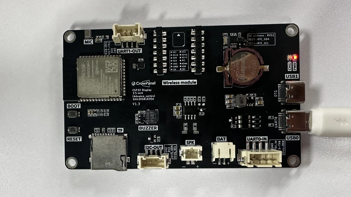
Connect the 3.5inch development board to the computer using a USB cable that supports data transfer.
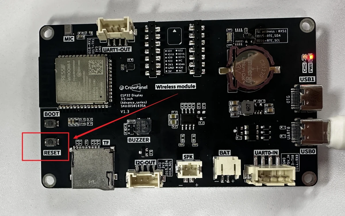
After flashing is complete, press RESET and observe the serial monitor to confirm that the output increments every second. The LCD not displaying Hello, World! is normal, because this lesson contains no LCD drawing code.
6. Key Code Explanation
counter holds the current number of outputs. It is defined in the global scope, so the incremented value is preserved after each execution of loop(). If it were changed to a local variable inside loop(), the number would repeatedly restart from the initial value, and a continuous count could not be formed.
setup() runs only once after the board resets. Serial.begin(9600) initializes the USB debug serial port; the serial monitor on the computer must use the same 9600 baud rate. If the baud rates do not match, common symptoms are garbled output, blank output, or incomplete log display.
void loop() {
  Serial.print("Hello, World! ");
  Serial.print("--- ");
  Serial.println(counter);

  counter++;
  delay(1000);
}
loop() runs repeatedly in the Arduino runtime. The first three lines form a complete log entry; println() adds a newline after the counter value; counter++ increments the number for the next output by 1; delay(1000) paces the output to roughly once per second, making it easy to observe stability with the naked eye. If the delay is removed, the serial port will scroll rapidly, making it difficult to judge whether the program is running normally.
7. Experimental Results
After a reset or power cycle, the serial monitor should display something like:
Acceptance criteria: the text shows no garbling; the number increases by 1 per line; adjacent outputs are spaced about 1 second apart; it runs continuously without interruption; after pressing RESET, it restarts from 0. Whether the LCD displays the lesson text is not part of this lesson's acceptance criteria.
8. Code Download
Code path: lesson-01/Serial_port_printing