3.5inch_Lesson03_LCD_Touch_LVGL_Lamp
1. Course Introduction
This lesson uses LovyanGFX to initialize the 3.5inch LCD and touchscreen, and loads the LVGL lamp control interface exported from SquareLine Studio. Once the program is running, the UI is displayed on the screen. When the ON / Off controls are touched, the UI event calls the lamp control function, the GPIO18 output state changes accordingly, and the serial port outputs logs containing the touch coordinates and the lamp status.
This lesson is a key step in moving from "serial output and audio playback" to "interactive on-screen control." Learners need to observe the LCD, touch, serial port, and GPIO18 at the same time, and understand how UI events are translated into real hardware actions.
2. Learning Objectives
- Be able to upload the project that includes the 3.5inch LCD, touch, LVGL, and UI files.
- Be able to explain the relationship among the LCD flush callback, the touch read callback, and
ui_init(). - Be able to understand the relationship between
set_lamp_state()and the GPIO18 lamp control output. - Be able to locate problems based on symptoms such as a black screen, unresponsive touch, or a lamp that will not turn on.
- Be able to re-export the SquareLine Studio UI file at the 3.5inch resolution of
480 × 320.
3. What You Need
- Hardware: CrowPanel Advance 3.5inch ESP32-S3 development board.
- Cable: a USB data cable that supports data transfer.
- Output load: a GPIO18 indicator LED or a safe external lamp control circuit.
- Software: Arduino IDE, with the ESP32 Arduino development environment configured in Lesson 01.
- Dependencies: course library files such as LVGL, LovyanGFX, and TAMC_GT911.
- UI tool: SquareLine Studio, used to recreate or export UI files.
- Project:
3_5LVGL.ino. - Resources: files such as
ui.c,ui.h,ui_Screen1.c,ui_events.c,ui_img_table_lamp_png.c, andtouch.hmust be kept in the same project directory.
Code and Resource Download
Code download: - lesson-03
Resource download: - table_lamp.png - lamp-svg.png


4. Software Operation Steps
Open the project 3_5LVGL.ino using Arduino IDE.
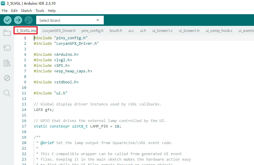
Note: Check the project file list and confirm that LovyanGFX_Driver.h, pins_config.h, touch.h, ui.c, ui.h, ui_Screen1.c, ui_events.c, and the image resource files are all in the same project directory.
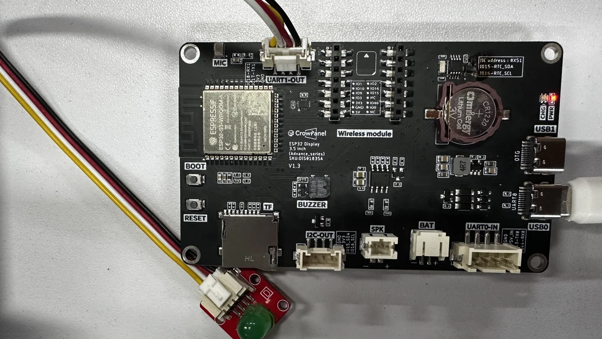
Connect the external LED, and use a USB cable that supports data transfer to connect the board to the computer.
Configure Arduino IDE. The commonly used settings are as follows:
-
Board:ESP32S3 Dev Module -
Port: select the serial port corresponding to the current board -
Flash Size:16MB (128Mb) -
PSRAM:OPI PSRAM -
Partition Scheme:Huge APP (3MB No OTA/1MB SPIFFS)
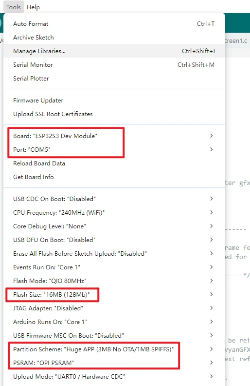
Note: If Arduino IDE reports a compilation error, go back to Lesson 01 first and check whether the ESP32 Core is version 3.3.8, and confirm that the board model, PSRAM, Flash Size, and course library files are all consistent.
Click Upload to compile and wait for the upload to finish. If it gets stuck at Connecting..., check for port conflicts and use the BOOT/RESET download mode as required by the board.
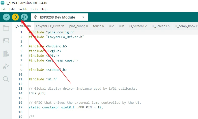
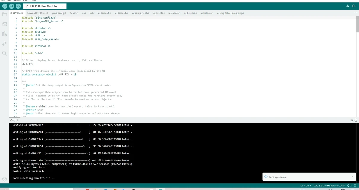
5. Hardware Operation Steps
Connect the external LED, and use a USB cable that supports data transfer to connect the board to the computer.
After flashing is complete, wait for the board to reset; the screen should display the lamp control UI you just built.
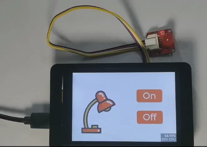
6. Key Code Explanation
static constexpr uint8_t LAMP_PIN = 18;

extern "C" void set_lamp_state(bool enabled) {
  digitalWrite(LAMP_PIN, enabled ? HIGH : LOW);
  Serial.println(enabled ? "Lamp ON" : "Lamp OFF");
}
set_lamp_state() lets the UI events exported from SquareLine Studio control the Arduino GPIO. If the on-screen control responds but the lamp does not change state, check the UI event binding, the GPIO18 wiring, and the load driving circuit.
lv_display_t *disp = lv_display_create(LCD_H_RES, LCD_V_RES);
lv_display_set_flush_cb(disp, my_disp_flush);
lv_indev_set_read_cb(indev, my_touchpad_read);
ui_init();
This code connects LVGL with the LCD, the touch input, and the UI resources. An abnormal screen flush callback will cause a black screen or a garbled display; an abnormal touch callback will cause the UI to display but not respond; and if ui_init() is not executed, the screen may light up but the lesson's interface will not be loaded.
size_t buffer_size = sizeof(lv_color_t) * LCD_H_RES * LCD_V_RES;
buf = (lv_color_t *)heap_caps_malloc(buffer_size, MALLOC_CAP_SPIRAM);
buf1 = (lv_color_t *)heap_caps_malloc(buffer_size, MALLOC_CAP_SPIRAM);
This project allocates the LVGL display buffer at the 3.5inch resolution of 480 × 320 and uses PSRAM to store the refresh data. If the PSRAM configuration is incorrect or the memory allocation fails, the board may reboot, show a black screen, or fail to refresh stably.
GPIO38 is used to turn on the screen backlight. If LCD initialization has completed but the backlight is not turned on, the screen may still appear black, so when troubleshooting a black screen you should check both the backlight and the screen flush callback.
7. UI Creation Steps
The UI in this section is built with SquareLine Studio. The official procedure is to first create an Arduino + TFT_eSPI type project, then add the lamp image, the On button, and the Off button, and finally bind the Lamp_on and Lamp_off callback functions to the two buttons respectively before exporting the UI files.
For downloading and basic installation of SquareLine Studio, refer to:
7.1 Create the SquareLine Project
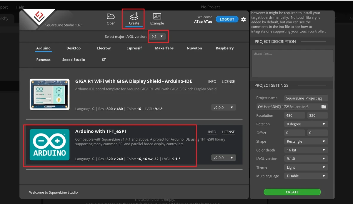
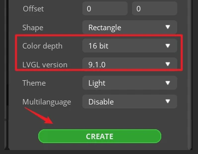
Open SquareLine Studio and click Create at the top. When creating a new project, you must select LVGL 9.1.0.
In the board category, select Arduino.
Select the Arduino with TFT_eSPI project template.
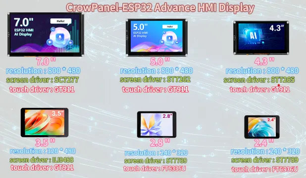
Confirm the resolution according to the screen size. The 3.5inch course project uses 480 x 320.
In the Project Settings on the right, set the project name and path, and confirm the key parameters:
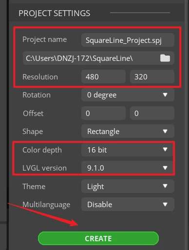
After confirming the parameters, click CREATE to create the project.
7.2 Import the Lamp Image Asset
After entering the project editing screen, switch to the Assets area at the bottom.
Click ADD FILE INTO ASSETS to import the lamp image asset into the project resources.
Of course, you can also choose to use a different image of your own.
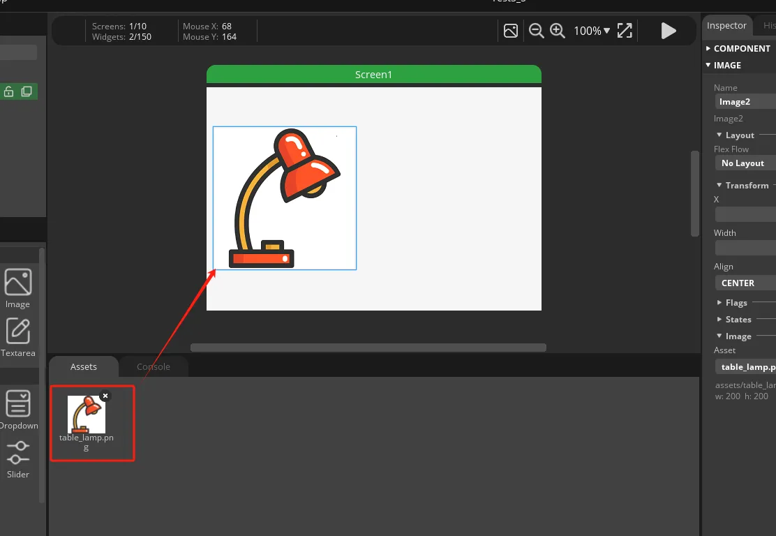
The image asset can be downloaded from the 3.5inch Arduino code repository: table_lamp.png.
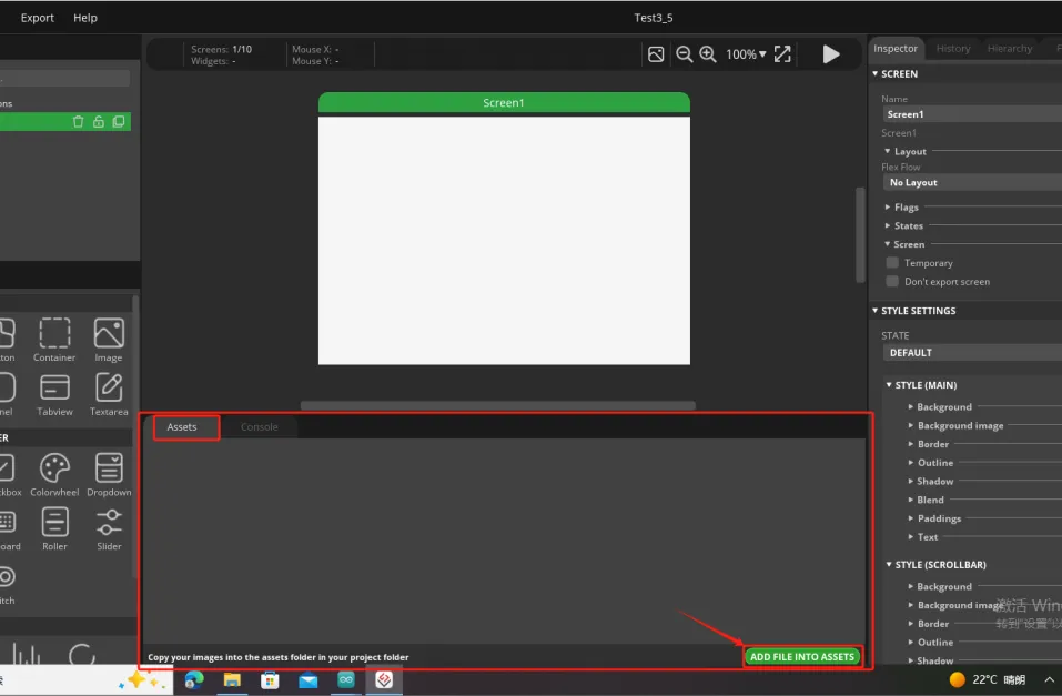
After the import is complete, drag the lamp image resource onto the Screen1 canvas. Adjust the position of the image on the canvas so that it sits on the left side of the screen, leaving space for the button area on the right.
7.3 Add the On Button
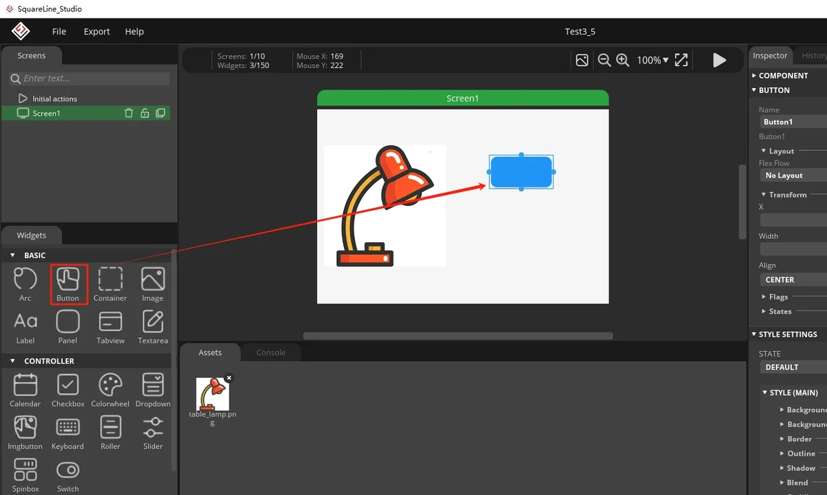
In the left Widgets > BASIC panel, select Button.
Drag the Button onto the right side of the canvas to serve as the On button.
Select the button and adjust its position and size in the Inspector on the right.
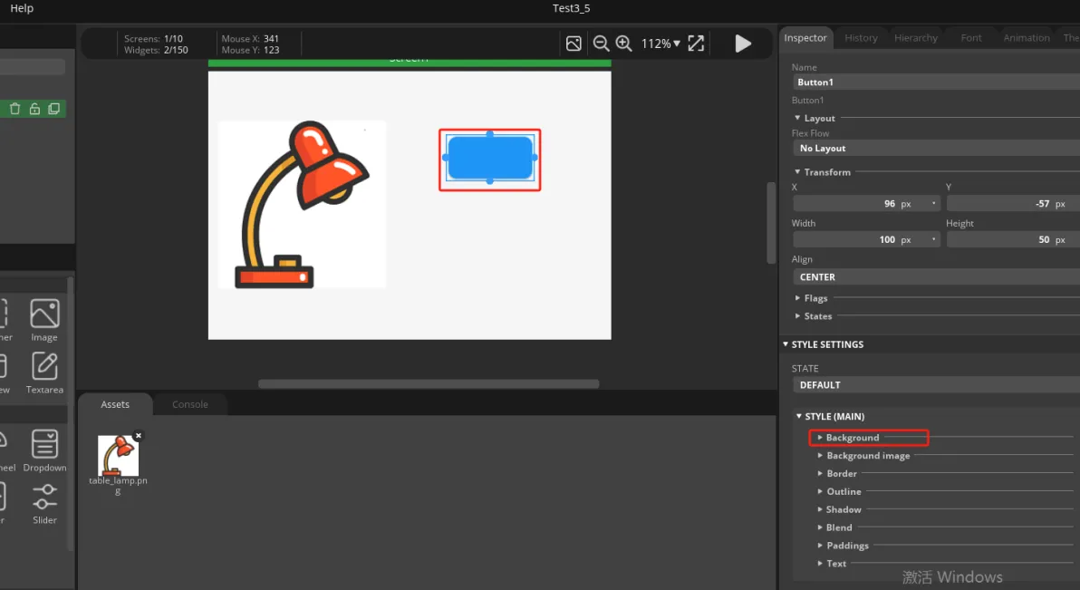
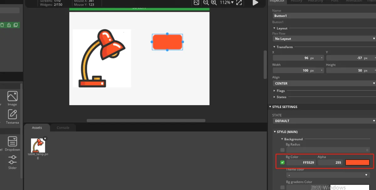
Expand STYLE (MAIN) > Background and set the button background color to orange-red; the official example color is FF5529.
Add a Label from the left Widgets > BASIC panel and drag it into the button.
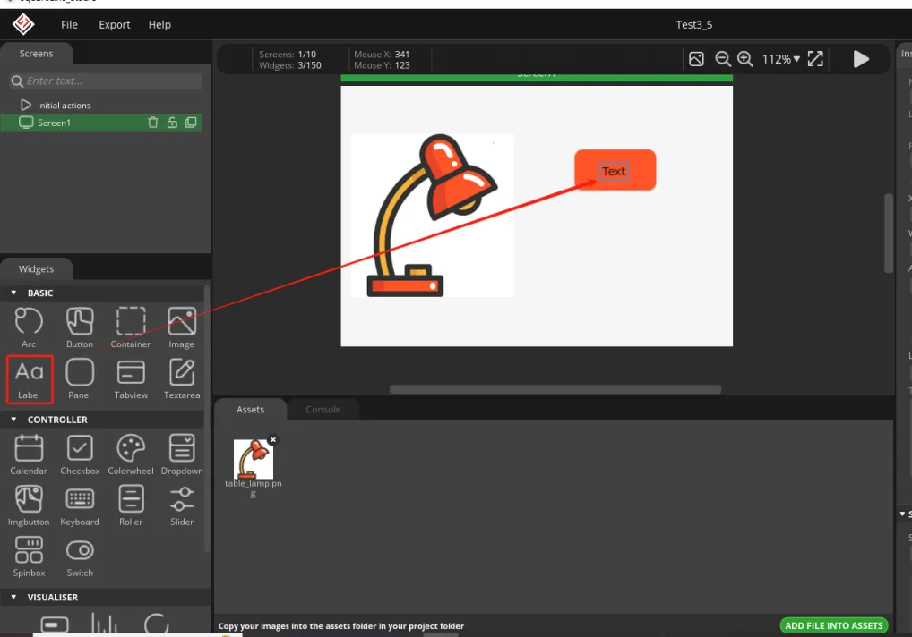
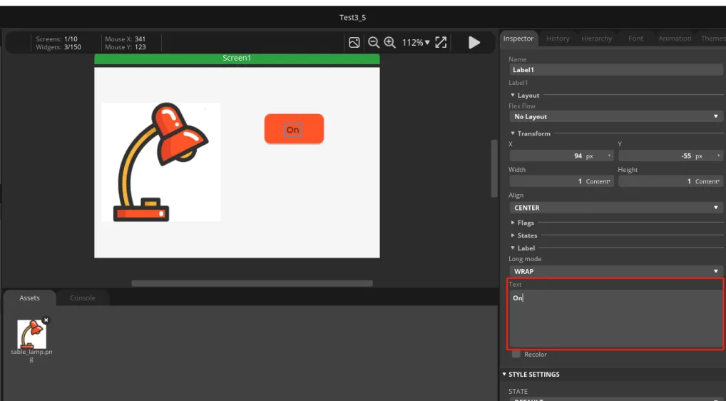
Select the Label and change its text to On in the text box on the right.
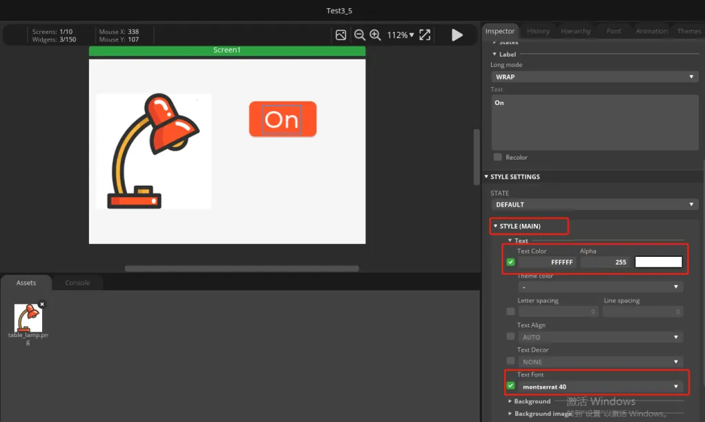
Adjust the Label style, set the text color to white, and choose an appropriate font size. Here we use montserrat 40.
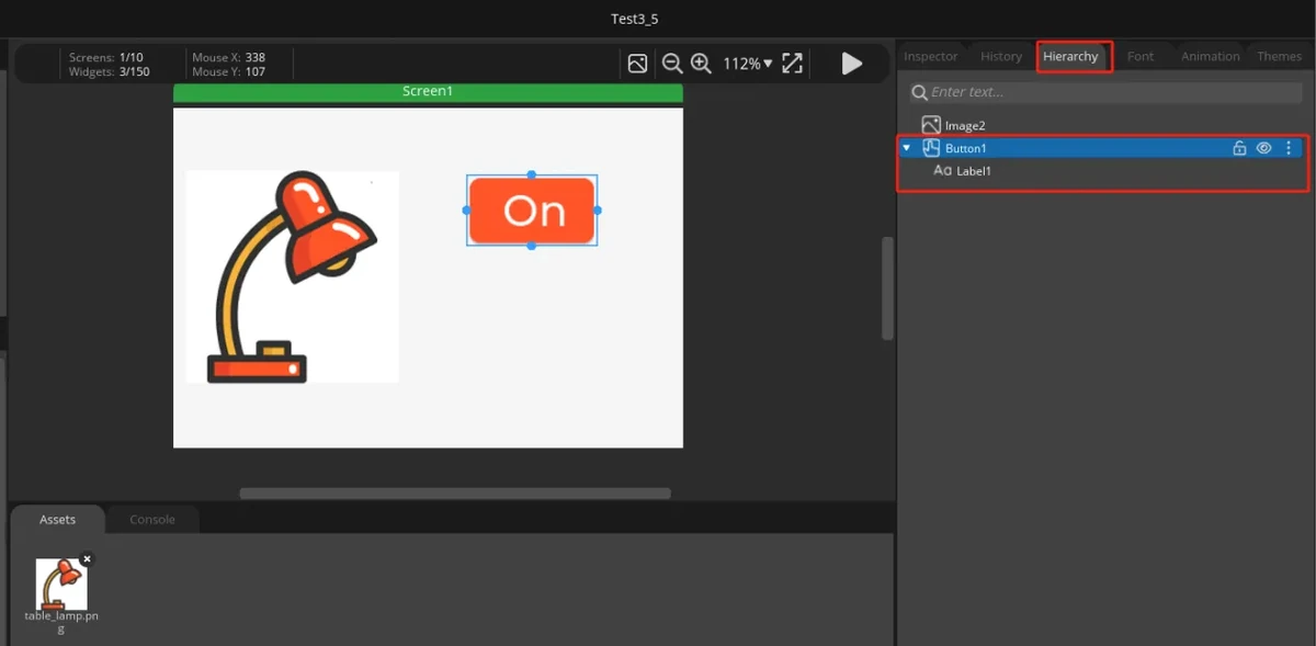
In the Hierarchy panel on the right, confirm that the Label is a child control of the Button.
7.4 Duplicate and Build the Off Button
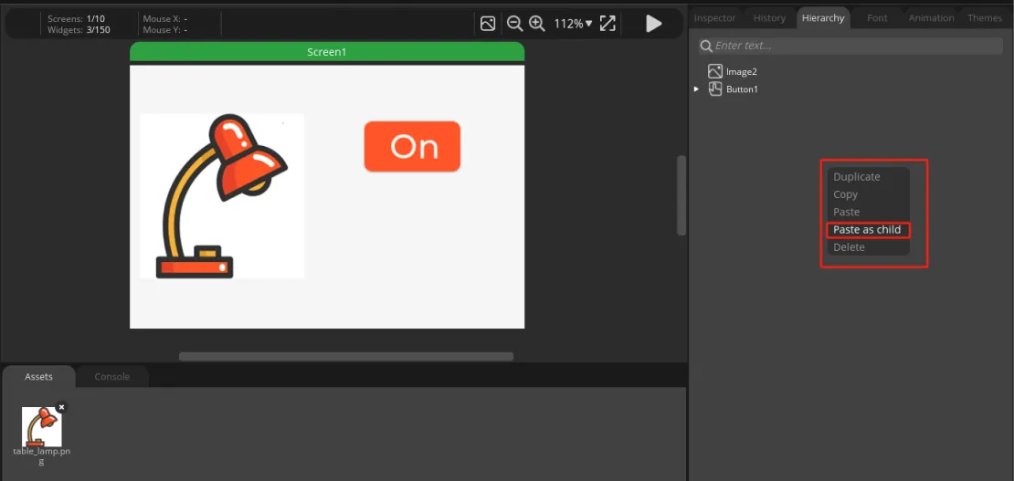
In the Hierarchy panel, select the completed Button1.
Open the more-options menu and choose Copy.
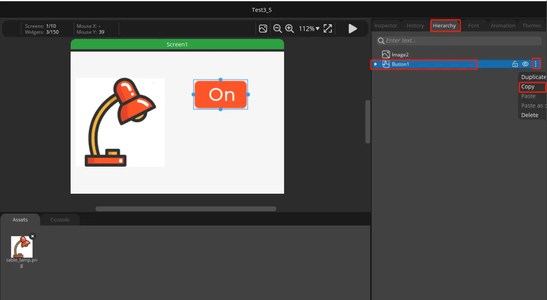
Paste it as a new button on the canvas or in the hierarchy. Use Paste as child to complete the duplication.
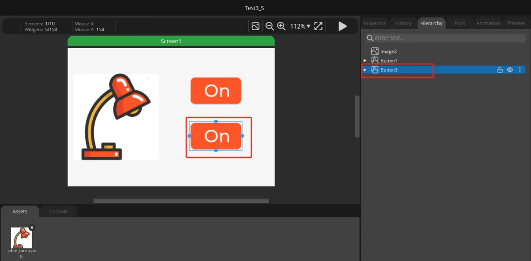
Move the duplicated button below the On button.
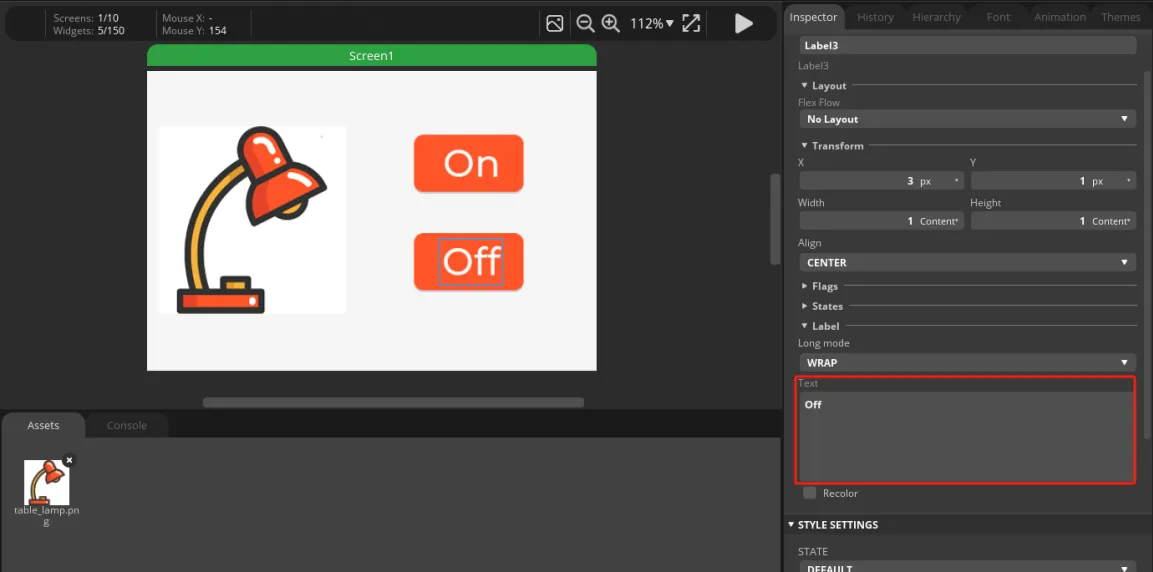
Select the Label in the new button and change its text to Off.
Adjust the position and background color of the two buttons as needed so that the On / Off buttons are arranged vertically on the right side.
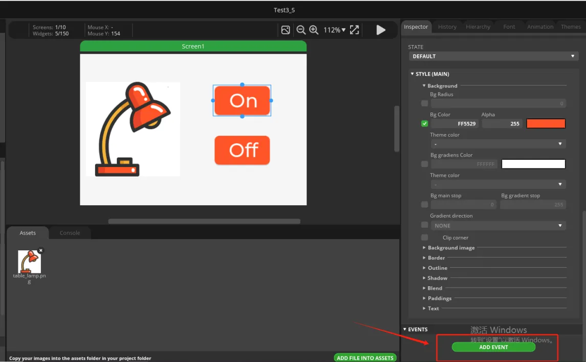
7.5 Configure Button Events
Select the On button and scroll the Inspector on the right to the EVENTS area.
Click ADD EVENT to add an event.
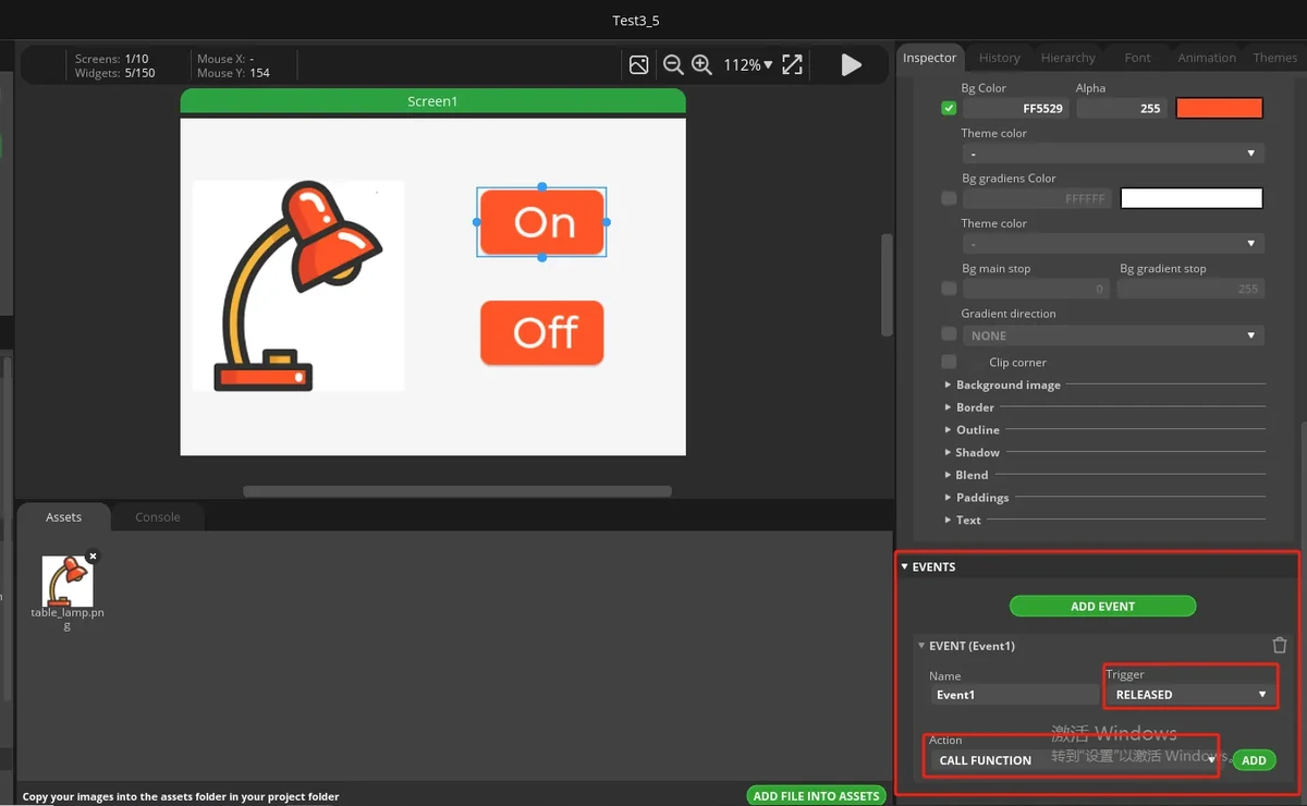
Set Trigger to RELEASED.
Set Action to CALL FUNCTION.
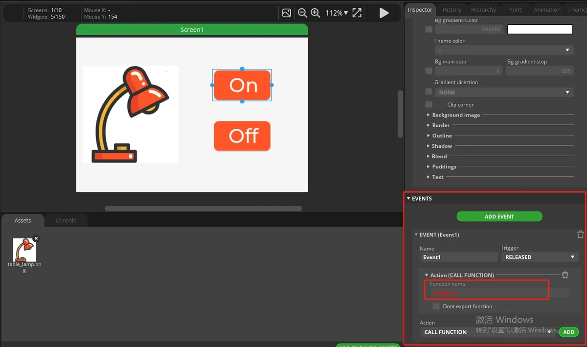
Enter the Function name:
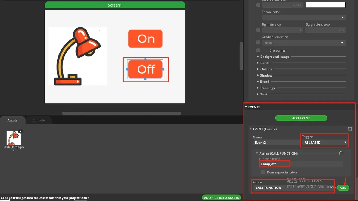
Select the Off button and add an event in the same way.
Set Trigger to RELEASED, set Action to CALL FUNCTION, and enter the Function name:
Note: The function name called by Call function must match the function name in the Arduino project exactly. In this lesson, the ON button uses Lamp_on and the Off button uses Lamp_off; a case mismatch in the function name will prevent the button from lighting the LED.
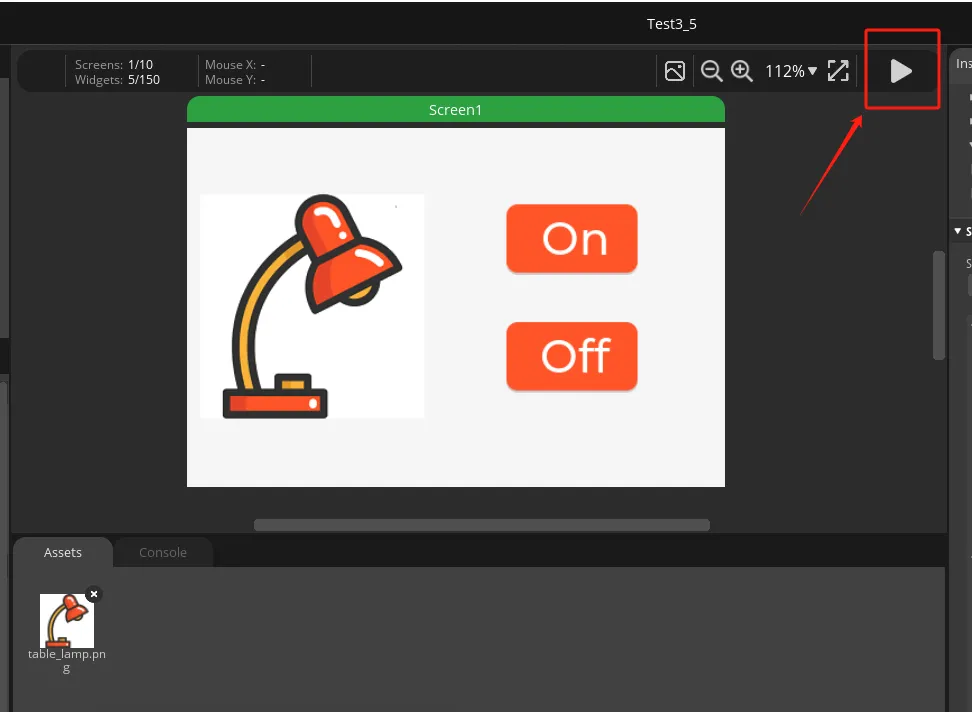
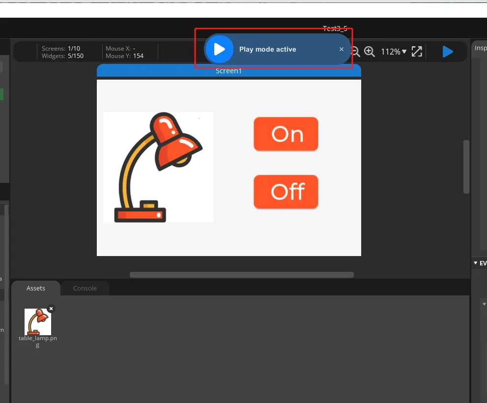
Click the play button in the top-right corner to enter preview mode. After adding the events, run the program and check whether the On / Off buttons can be clicked normally.
7.6 Set the Export Path
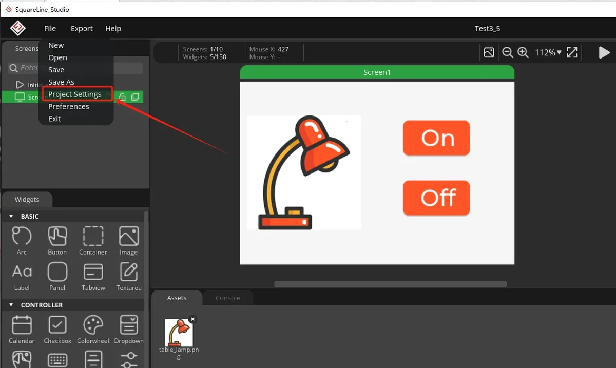
Click File > Project Settings to open the project settings.
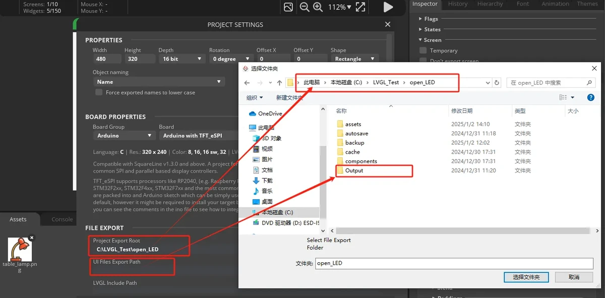
Set the export path in FILE EXPORT. In the example, Project Export Root points to the SquareLine project directory, and UI Files Export Path points to the Output folder.
Set LVGL Include Path to:
Check Flat export (exports all files to one folder), then click APPLY CHANGES.
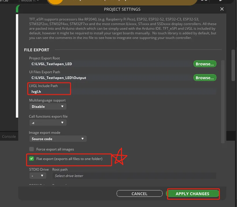
Note: It is recommended to check Flat export so that the exported UI files are grouped in a single folder, which makes it less likely to miss files when copying them into the Arduino project later.
7.7 Export the UI Files and Copy Them into the Arduino Project
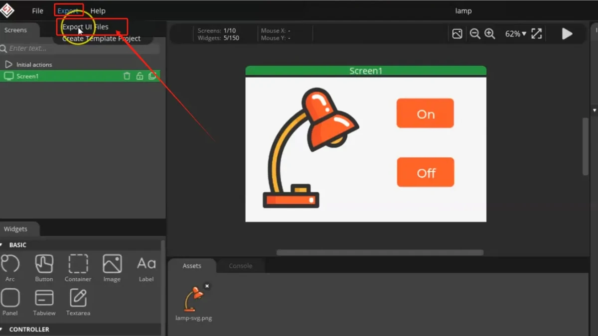
Click Export > Export UI Files in the top menu.
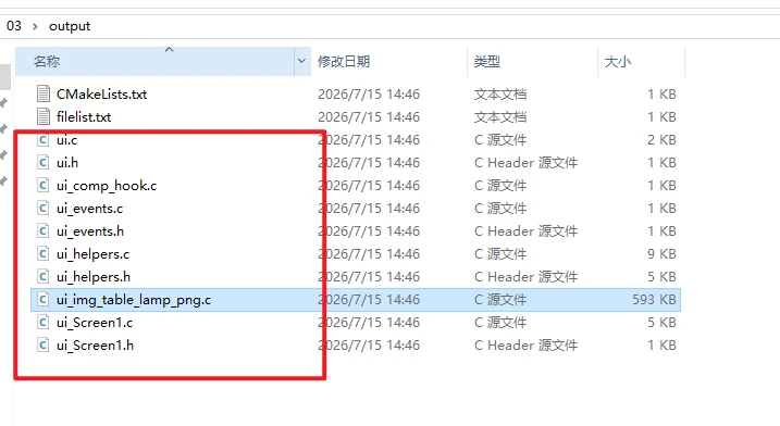
Open the exported Output folder and confirm that it contains the UI source files, event files, helper files, and image resource files. Common files include:
ui.c
ui.h
ui_events.c
ui_events.h
ui_helpers.c
ui_helpers.h
ui_Screen1.c
ui_comp_hook.c
ui_img_table_lamp_png.c
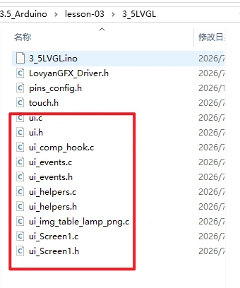
Copy the exported UI files into the Arduino project directory 3_5LVGL, that is, to the same level as 3_5LVGL.ino, LovyanGFX_Driver.h, pins_config.h, and touch.h.
8.Experimental Observation
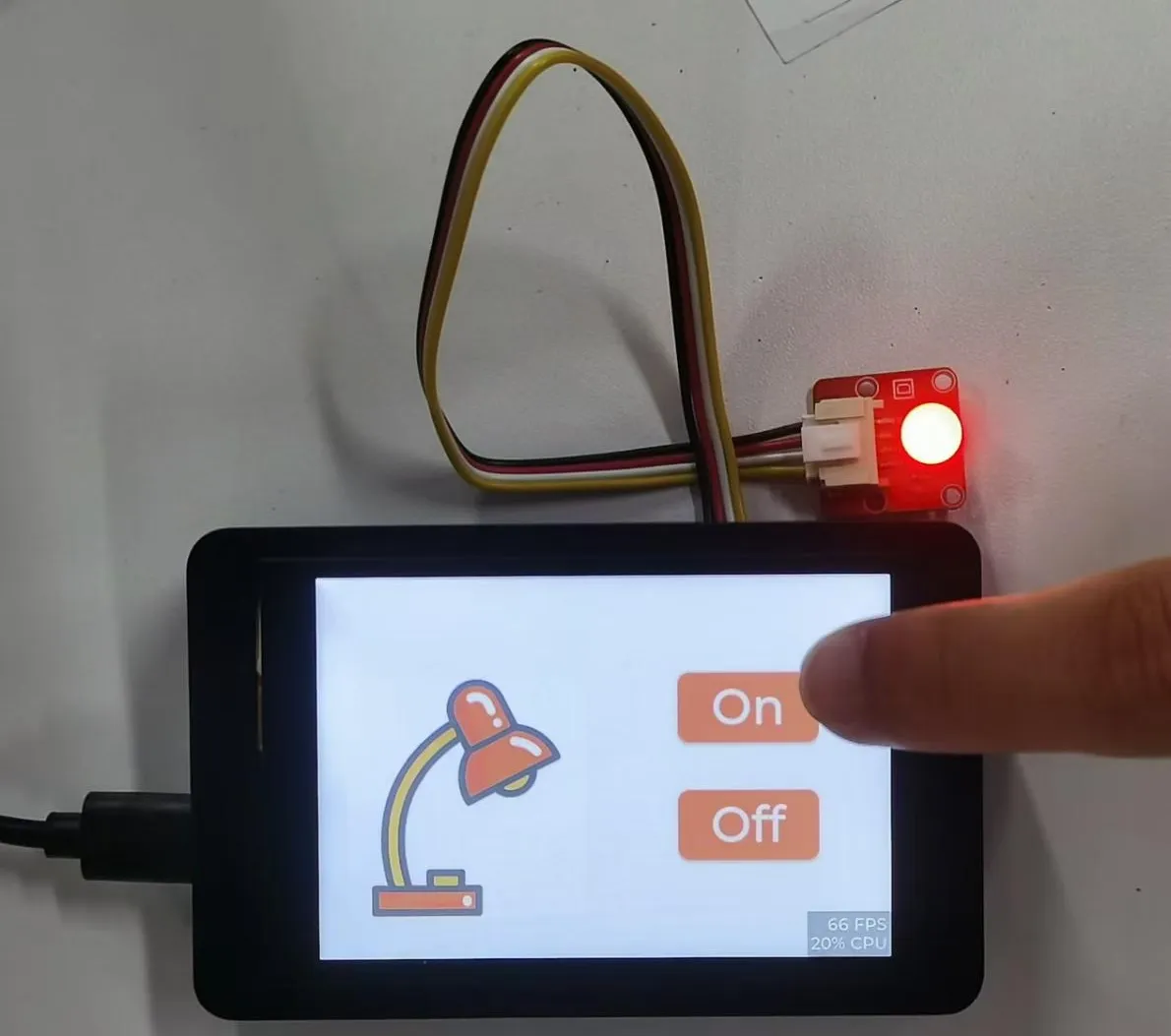
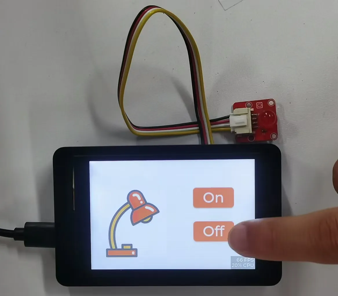
Click the ON and Off buttons on the screen and observe whether the bulb/LED connected to the UART1 interface toggles on and off.
9. Code Download
- Code path: lesson-03
- Lesson03 bulb image: table_lamp.png
- Lesson03 bulb asset backup: lamp-svg.png