Lesson 01: Serial Output of "Hello World"
1. Course Objectives
In this lesson, you will complete the initial setup of the Arduino IDE, create and upload your first ESP32-P4 project, and then use the UART0 serial monitor to print Hello World! once per second.
After completing this lesson, you should be able to:
- Install and verify the ESP32 Arduino Core.
- Correctly select
ESP32P4 Dev Module, the serial port, and the P4 upload parameters. - Distinguish
setup(), which runs only once, fromloop(), which runs continuously. - Complete the verification and upload process, and view the serial output at a baud rate of 115200.
- Troubleshoot common issues based on compilation, upload, and serial messages.
2. Preparation
- Arduino IDE 2.x. The screenshots in this lesson use Arduino IDE 2.3.x; other compatible 2.x versions operate essentially the same way.
- ESP32 Arduino Core 3.3.3, or a compatible version specified by the course package.
- One CrowPanel Advanced 5-inch ESP32-P4 HMI AI Display development board.
- One USB-C cable that supports data transfer; a power-only cable cannot upload programs.
- No external modules are required for this lesson; the project folder only needs to keep the
.inofile that shares the same name as the folder.
Reference code link: https://github.com/Elecrow-RD/-CrowPanel-Advanced-5inch-ESP32-P4-HMI-AI-Display-800x480-IPS-Touch-Screen/tree/master/example/V1.0
3. First-Time Project Setup
When using the board for the first time, complete the configuration in the order described in this section. First confirm the development environment and project, then connect the hardware, select the board and port, and finally compile and upload.
3.1 Confirm the Arduino IDE Version
Launch the Arduino IDE, open Help > About Arduino IDE, and confirm that you are using Arduino IDE 2.x. The version number shown in the screenshot is for demonstration only, and does not need to match the screenshot exactly.
Software installation: Download_Arduino_IDE - Elecrow Wiki

3.2 Install the ESP32 Board Support Package
After the installation is completed, open the Arduino IDE. First, randomly open a project.

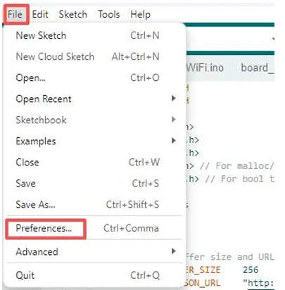
Go to "Preferences"
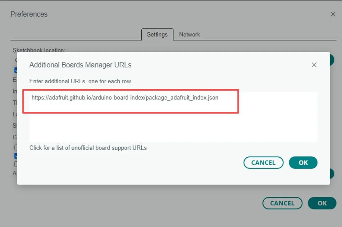
Configure "Additional Boards Manager URLs"

Add this in
https://adafruit.github.io/arduino-board-index/package_adafruit_index.json
Remember to save!
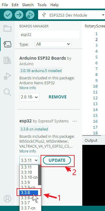
- Click Board Manager on the left side.
- Search for
esp32. - Locate esp32 by Espressif Systems, select the version required by the course, and install it.
- After installation, close the Board Manager; if the corresponding version already shows as
installed, there is no need to reinstall.
The reference image shows the entry point, search, and version status of the Board Manager. For this P4 lesson, version 3.3.3 should be installed.
3.3 Create or Open the Complete Project
In the Arduino IDE, select File > New Sketch and save it as Lesson01-Print_Hello_World; alternatively, you can directly open Lesson01-Print_Hello_World.ino from the course code.
An Arduino sketch requires the project folder name to match the main .ino file name. For example:
If the IDE prompts you to automatically create a folder with the same name, confirm and proceed.

Write the following code into the sketch and save it:
void setup() {
    // put your setup code here, to run once:
    Serial.begin(115200);  // Init Uart
}

void loop() {
  Serial.print("Hello World!\r\n");
  delay(1000);
}
3.4 Connect the Board Using UART0
Connect a USB-C cable that supports data transfer to the port labeled UART0 on the board, then connect it to your computer.

Important: Arduino programs are uploaded via UART0.
UART3-INis only used for external power supply or general serial communication and cannot replace UART0 for flashing programs.
3.5 Select the Board and Port
Open Tools > Board > esp32 and select ESP32P4 Dev Module.

Then open Tools > Port and select the COM port that newly appears after connecting the board. If you are unsure which port to choose, unplug the data cable to observe which port disappears, then reconnect and select the port that reappears.
3.6 Verify the Upload Parameters
Check each item in the Tools menu:
- Board:
ESP32P4 Dev Module - Core Debug Level:
Info - Flash Frequency:
80MHz - Flash Mode:
QIO - Flash Size:
16MB (128Mb) - Partition Scheme:
16M Flash (3MB APP/9.9MB FATFS) - PSRAM:
Enabled - Upload Mode:
UART0 / Hardware CDC - USB Mode:
Hardware CDC and JTAG - Port: the
COMport that actually corresponds to the board

3.7 Import the Library Files We Need to Use
Open File > Preferences and note the "Sketchbook location".
Close the Arduino IDE, then confirm that the libraries folder exists in that directory.

Library file link for this project: -CrowPanel-Advanced-5inch-ESP32-P4-HMI-AI-Display-800x480-IPS-Touch-Screen/example/V1.0/Arduino_Code_5inch at master · Elecrow-RD/-CrowPanel-Advanced-5inch-ESP32-P4-HMI-AI-Display-800x480-IPS-Touch-Screen
After determining the location where the library files are stored Copy all the library files contained in the downloaded "libraries" file to the "C:\Users\Username\Documents\Arduino\libraries" folder on your local computer.

How to add the library files: https://www.elecrow.com/wiki/Arduino_IDE_Library_Import_Guide.html
Note: The course dependency libraries need to be placed in the libraries directory under the Arduino Sketchbook folder. After copying is complete, restart the Arduino IDE to prevent the IDE from continuing to use the old library index.
Note: If there is no "libraries" folder in your path, please create one yourself.
3.8 Verify Compilation Before Uploading
- Click the Verify (checkmark) button in the upper left corner.
- Wait for the output area to show that compilation is complete; if errors appear, resolve them first and do not upload directly.
- Click the Upload (right arrow) button.
- Wait until writing reaches 100%, and see the upload complete or auto-reset message.

If it stays stuck at Connecting... for a long time, first confirm the UART0 connection, the data cable, and the COM port; if it still cannot connect, hold down the BOOT button on the board and release it once writing begins.
3.9 Open the Serial Monitor to Verify the Result
Click the Serial Monitor in the upper right corner and set the baud rate to 115200. The baud rate must match Serial.begin(115200).


Under normal conditions, the monitor will continuously display:
Adjacent lines are spaced about 1 second apart.
4. Core Code Explanation
4.1 setup(): Runs Only Once
After the board is powered on or reset, setup() runs only once. Serial.begin(115200) initializes the serial port and sets the communication rate to 115200 bit/s, which must match the baud rate selected in the Arduino Serial Monitor.
4.2 loop(): Runs Continuously and Repeatedly
void loop() {
    // put your main code here, to run repeatedly:
    static int i = 0;
    Serial.printf("Hello world: %d\n", i++);   //print "Hello World!"
    delay(1000);    // Delay 1 second
}
The Arduino framework calls loop() repeatedly. static int i = 0 creates a counter that is initialized only once and retains its value between calls to loop(). Serial.printf("Hello world: %d\n", i++) prints Hello world: followed by the current counter value, then increments the counter for the next output. \n starts a new line, and delay(1000) pauses for 1000 ms, so a new numbered line is printed approximately once per second.

5. Acceptance Criteria
- The project can complete verification compilation without errors.
- The program can be uploaded via UART0 and auto-reset.
- After the Serial Monitor is set to a baud rate of 115200, it continuously displays
Hello World!. - The time interval between adjacent output lines is approximately 1 second.
6. Common Troubleshooting
- No port available: Replace the USB-C cable with one confirmed to support data transfer, and check whether it is connected to UART0.
- Upload stuck at
Connecting...: Reselect the actual COM port; if necessary, hold BOOT and release it once writing begins. - ESP32P4 not found during compilation: Go back to the Board Manager and confirm that
esp32 by Espressif Systemsof the version required by the course has been installed. - Garbled characters on the serial port: Change the Serial Monitor to a baud rate of 115200, then press RESET once.
- Only startup logs, no
Hello World!: Confirm that the.inoopened and uploaded is the one for this lesson, then verify and upload again. - Incorrect output speed: Check whether
delay(1000)has been modified; 1000 ms equals 1 second.