Lesson01_Arduino_LVGL_Rotary: Display, Touch, and Multi-Page Interaction on the 1.28-inch Rotary Screen
1. Course Introduction
This lesson uses the Arduino IDE to drive the CrowPanel 1.28inch-HMI ESP32 Rotary Display.
The project uses LovyanGFX to control the 240 × 240 GC9A01 round LCD, reads touch coordinates via the CST816D, loads the exported multi-page UI using LVGL 9.1.0, and uses FreeRTOS tasks to handle the rotary encoder and the five NeoPixel RGB LEDs.
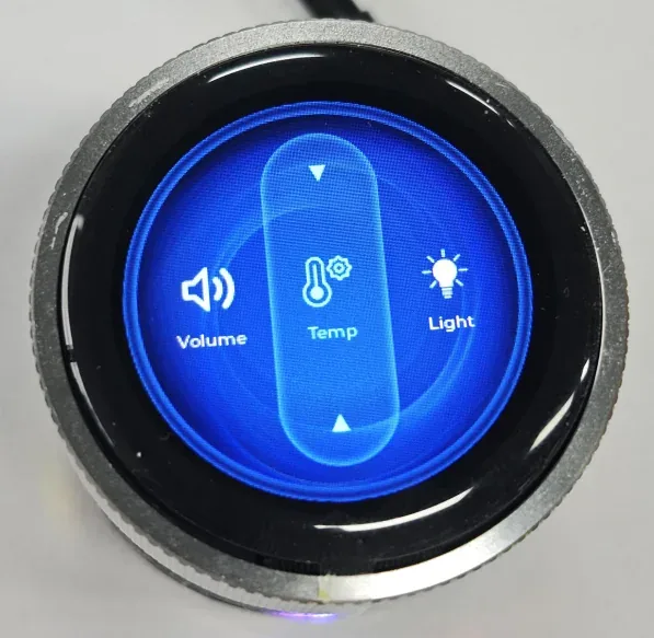
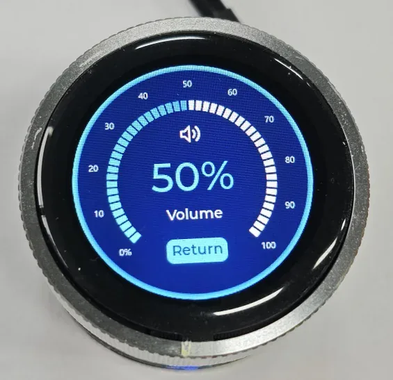
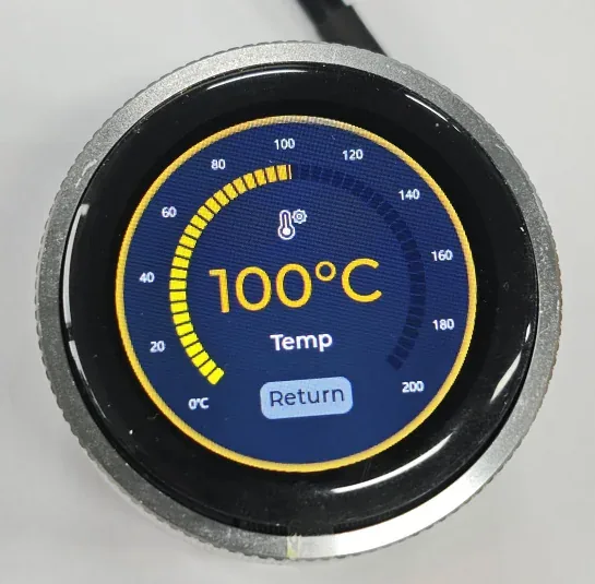
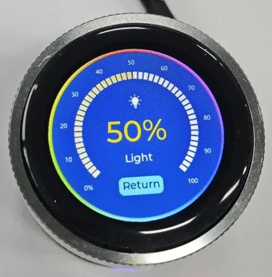
After the program is flashed and reset, the screen displays a startup page and enters the main menu. The main menu contains three items: Volume, Temp, and Light. Rotating the knob moves the selection; a single click enters the detail page. On the detail page, rotating the knob or touching the arc adjusts the value; double-clicking the knob returns to the main menu. Volume and Temp demonstrate UI value adjustment; Light converts the 0%–100% value into a PWM duty cycle on GPIO46, thereby changing the screen backlight. The five RGB LEDs simultaneously cycle through flowing, blinking, and color-breathing effects in the background.
This lesson validates the complete interaction chain consisting of screen power, SPI DMA refresh, PSRAM double buffering, I²C touch, the LVGL interface, the knob event queue, PWM backlight, and NeoPixel lighting effects.
2. Learning Objectives
- Be able to configure the ESP32-S3, Flash, PSRAM, and the Arduino and library environment specified by the project.
- Be able to explain the relationship among GC9A01 display, CST816D touch, the LVGL refresh callback, and UI files.
- Be able to compile and flash the complete project, and determine whether the display chain is functioning properly based on the startup page and main menu.
- Be able to use rotation, single click, double click, and touch to complete page selection, value adjustment, and return operations.
- Be able to troubleshoot common issues based on the interface, screen backlight, RGB LEDs, and serial logs.
3. Preparations
3.1 Hardware
- One CrowPanel 1.28inch-HMI ESP32 Rotary Display.
- One USB data cable that supports data transfer.
- One computer with the Arduino IDE installed.
This project uses the on-board GC9A01 LCD, CST816D touch controller, rotary encoder, encoder button, and five NeoPixel RGB LEDs, so no external modules of these types are required.
Product information: CrowPanel 1.28inch-HMI ESP32 Rotary Display
3.2 Software and Versions
- Arduino IDE 2.3.6.
- ESP32 Arduino Core 3.3.8.
- LVGL 9.1.0.
- LovyanGFX 1.2.26.
- Adafruit NeoPixel 1.15.1.
- The project's bundled CST816D driver,
lv_conf.h, and UI files.
The project already includes the dependent libraries. Do not additionally install other versions of libraries with the same name, otherwise the Arduino IDE may prioritize loading the wrong version.
Course code:
CrowPanel 1.28inch Arduino Examples
Library files required by the code:
3.3 Project Files That Must Be Preserved
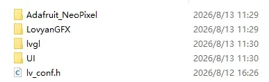
RotaryScreen_1_28/RotaryScreen_1_28.ino: Main program.RotaryScreen_1_28/CST816D.cppandCST816D.h: Touch controller driver.libraries/UI/: LVGL pages, image assets, and generated code.libraries/lvgl/,libraries/LovyanGFX/,libraries/Adafruit_NeoPixel/: Version-specific dependencies.libraries/lv_conf.h: LVGL configuration.
Do not copy only the .ino file. If the touch driver, UI directory, or image assets are missing, the project will fail to compile completely or will not display the interface for this lesson.
4. Software Operation Steps
Step01: Install ESP32
Arduino IDE installation guide: Get Started with Arduino IDE
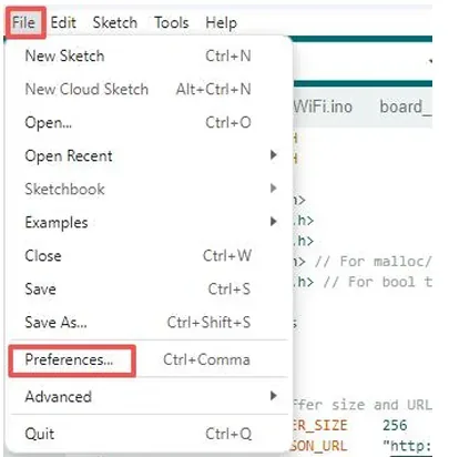
After installation, open the Arduino IDE and go to "Preferences".
Configure "Additional Boards Manager URLs".
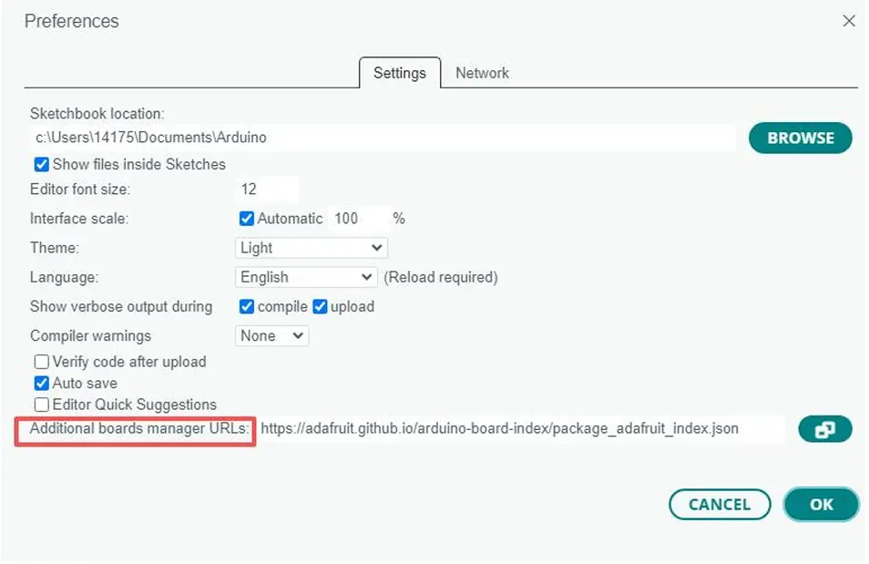
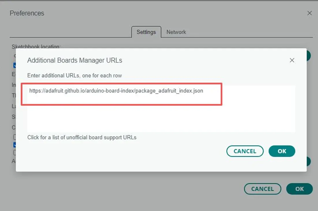
Add this in:
https://adafruit.github.io/arduino-board-index/package_adafruit_index.json
Remember to save!
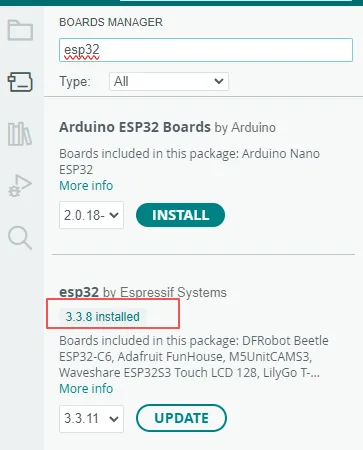
- Click Board Manager on the left sidebar.
- Search for
esp32. - Find esp32 by Espressif Systems, select the version required by the course, and install it.
- After installation completes, close the Board Manager; if the corresponding version already shows as
installed, there is no need to reinstall.
The rotary screen product's Arduino IDE code all uses the ESP32-3.3.8 version.
Step02: Import Library Files
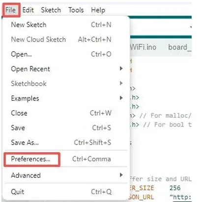
Open File > Preferences and note the "Sketchbook location".
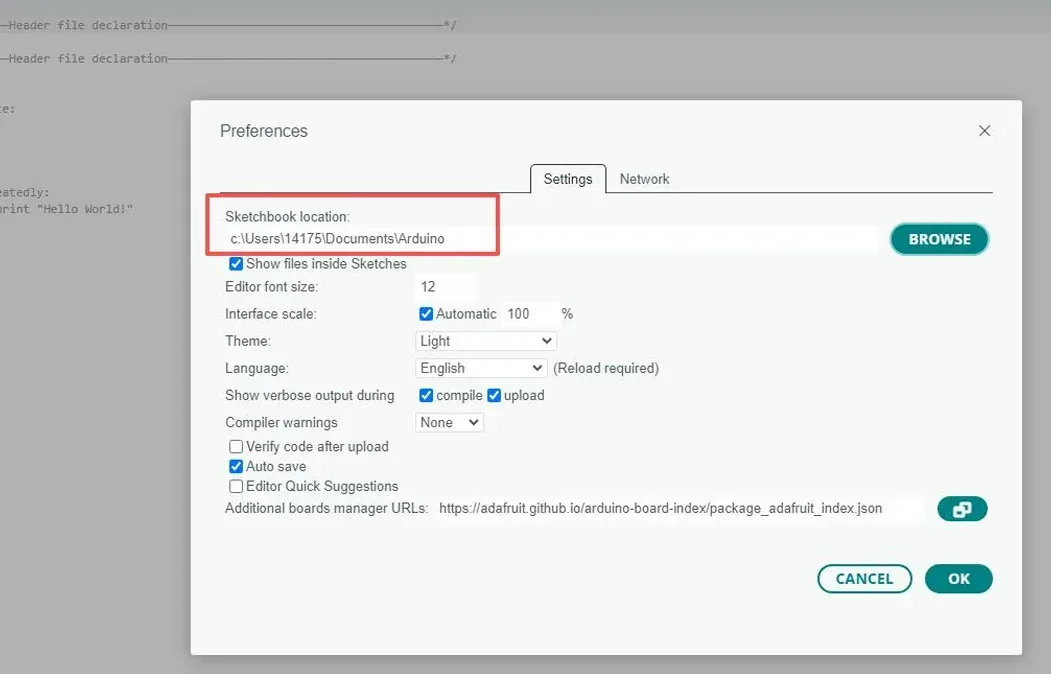
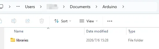
Open this file system path.
Our project's library file link:
After determining the location where the library files are stored, copy all the library files contained in the downloaded "libraries" folder to the "C:\Users\Username\Documents\Arduino\libraries" folder on your local computer.
For example: (refer to the method in the figure below, and copy the library files you need to that path.)
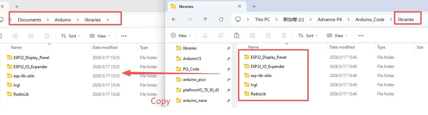
How to add the library files: https://www.elecrow.com/wiki/Arduino_IDE_Library_Import_Guide.html
Note: The course dependency libraries must be placed in the libraries directory under the Arduino Sketchbook folder. After copying is complete, restart the Arduino IDE to prevent it from continuing to use the old library index.
Note: If there is no "libraries" folder in your path, please create one yourself.
Step03: Export UI Files from SquareLine Studio
You can click the link below to download the SquareLine Studio project we provide.
SquareLine Studio operation guide:
https://www.elecrow.com/wiki/Get_Started_with_SquareLine_Studio.html
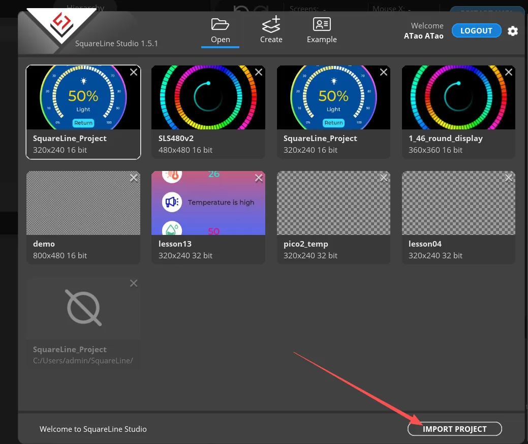
After downloading SquareLine Studio, click Import.
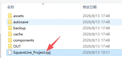
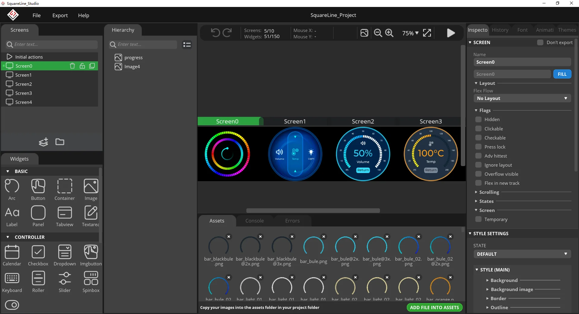
Export our project, and you will be able to see the specific UI interface information.
Step04: Expand the Partition Table
Because the rotary screen's Arduino IDE code is combined with the UI files generated by SquareLine Studio, the overall project is fairly large, and the partition table provided in the current ESP32 library is insufficient to support running the entire project, so the partition table needs to be expanded.
You can first download the partition table content we provide:
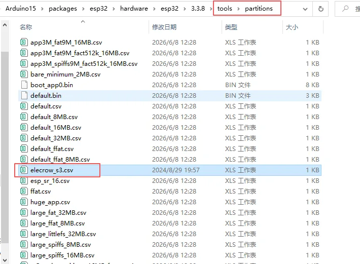
After downloading the partition table file, open your local ESP32 download path.
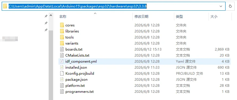
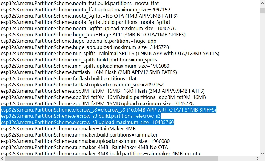
Open the boards.txt file in the partition table file we provide at the link above, and copy its contents.
esp32s3.menu.PartitionScheme.elecrow_s3=elecrow_s3 (10.0MB APP with OTA/1.31MB SPIFFS)
esp32s3.menu.PartitionScheme.elecrow_s3.build.partitions=elecrow_s3
esp32s3.menu.PartitionScheme.elecrow_s3.upload.maximum_size=10485760
Then open the boards.txt in your local path.
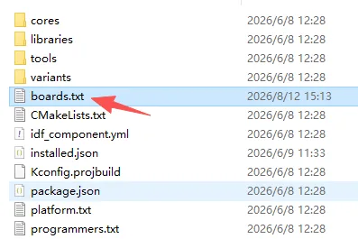
Copy the content above to the corresponding location; do not place it arbitrarily—refer to the position shown in the figure.
Then go to this path and copy the partition table file we provide into it.
Then close all your Arduino IDE programs, and we recommend restarting the computer.
Step05: Open the Code, Set Parameters, and Upload
The code link has been provided above; please download it.
Then double-click this ino file to open the entire project.
Confirm that
RotaryScreen_1_28.ino,CST816D.cpp, andCST816D.hare located in the same sketch directory.
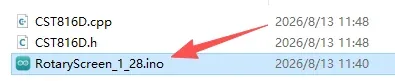
Check the Arduino library directory and confirm that UI, lvgl, LovyanGFX, Adafruit_NeoPixel, and lv_conf.h have all been preserved.
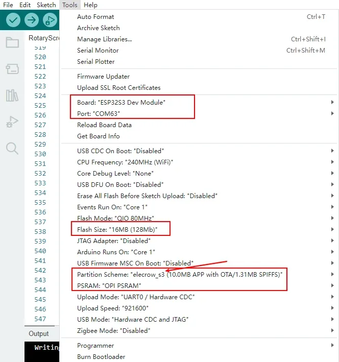
In the Tools menu, select ESP32S3 Dev Module and the serial port number you are using, and set Flash Size to 16 MB (128 Mb), Partition Scheme to the elecrow_s3 we provided above, and PSRAM to OPI PSRAM.
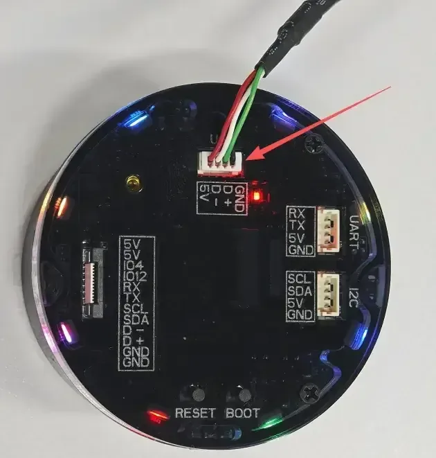
Connect the rotary screen using a USB cable that supports data transfer, select the newly appearing serial port under Tools > Port, then click Upload Code.
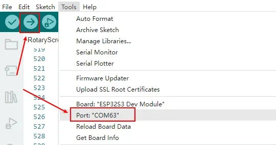
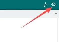
After uploading the code, if you need to open the Serial Monitor, you can click the icon in the upper-right corner of the Arduino IDE.
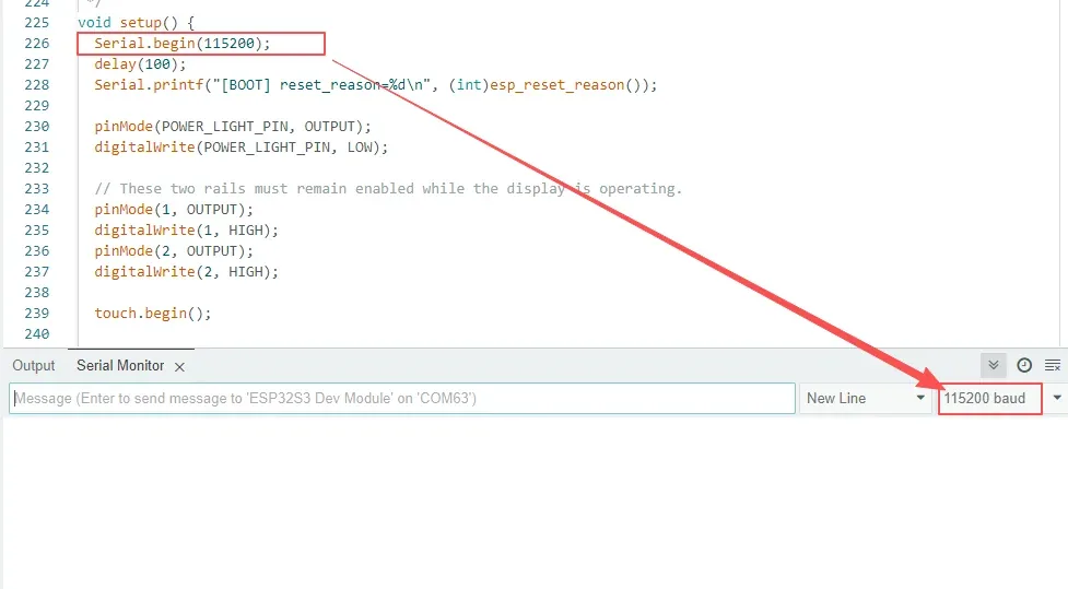
Then set the serial baud rate configured in your code.
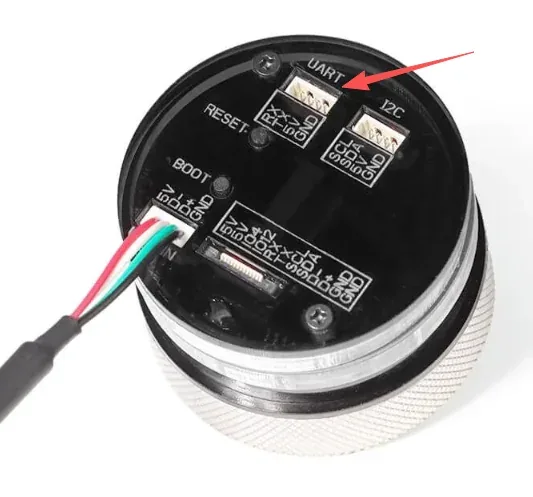
However, due to hardware limitations, if you connect only via a power cable, you may not see any serial output. You will need to purchase a serial-to-TTL hardware tool and use the UART interface on the 1.28-inch rotary screen to view the relevant serial information.
5. Hardware Operation Steps
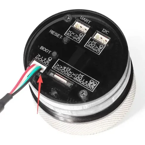
Step01: With the development board powered off, inspect the USB connector, the 240×240 round screen, the knob, and the five peripheral RGB LEDs to confirm that the connectors are not damaged and that there are no metal foreign objects on the board surface.
Step02:
In the main menu, rotate the knob and observe the blue selection moving among Volume, Temp, and Light; single-click the knob to enter the selected detail page.
Step03:
Connect the CrowPanel 1.28inch-HMI ESP32 Rotary Display to the computer using a USB cable that supports data transfer.
After flashing and resetting, observe the round LCD display area; the images illustrate the viewing position of the 1.28-inch screen. During the actual operation of this lesson, wait for the startup page to finish, and use the appearance of the Volume, Temp, and Light main menu as the acceptance criterion.
Step04:
On the detail page, rotate the knob or drag the arc with your finger to confirm that the value and the arc change in sync. Double-click the knob to return to the main menu. Do not touch the screen with sharp objects.
6. Key Code Explanation
6.1 GC9A01 LCD and SPI Bus
class LGFX : public lgfx::LGFX_Device {
  lgfx::Panel_GC9A01 _panel_instance;
  lgfx::Bus_SPI _bus_instance;

 public:
  LGFX(void) {
    auto bus_cfg = _bus_instance.config();
    bus_cfg.spi_host = SPI2_HOST;
    bus_cfg.spi_mode = 0;
    bus_cfg.freq_write = 80000000;
    bus_cfg.freq_read = 20000000;
    bus_cfg.spi_3wire = true;
    bus_cfg.dma_channel = SPI_DMA_CH_AUTO;
    bus_cfg.pin_sclk = 10;
    bus_cfg.pin_mosi = 11;
    bus_cfg.pin_miso = -1;
    bus_cfg.pin_dc = 3;
    _bus_instance.config(bus_cfg);
    _panel_instance.setBus(&_bus_instance);

    auto panel_cfg = _panel_instance.config();
    panel_cfg.pin_cs = 9;
    panel_cfg.pin_rst = 14;
    panel_cfg.memory_width = 240;
    panel_cfg.memory_height = 240;
    panel_cfg.panel_width = 240;
    panel_cfg.panel_height = 240;
    panel_cfg.invert = true;
    _panel_instance.config(panel_cfg);
    setPanel(&_panel_instance);
  }
};
The global LGFX object executes this constructor when created. SPI2 operates in mode 0, with GPIO10 providing the clock, GPIO11 sending pixel and command data, and GPIO3 distinguishing command from data. The panel uses GPIO9 for chip select and GPIO14 for reset. The write frequency is 80 MHz, and the DMA channel is auto-assigned. The GC9A01's memory and display area are both set to 240×240, and color inversion is enabled to match the actual panel.
These parameters determine whether the screen can display normally. Incorrect pins or panel type typically manifest as a black screen, white screen, or garbled display; incorrect dimensions cause cropping or coordinate misalignment; incorrect color inversion settings cause abnormal colors. When troubleshooting, first verify the product model, the screen power GPIO1/GPIO2, the backlight GPIO46, and this SPI configuration—do not blindly raise the SPI frequency.
6.2 LVGL Double Buffering and DMA Screen Refresh
static const uint32_t screenWidth = 240;
static const uint32_t screenHeight = 240;

size_t buffer_size = screenWidth * screenHeight * sizeof(uint16_t);
buf = (uint8_t *)heap_caps_malloc(buffer_size, MALLOC_CAP_SPIRAM);
buf1 = (uint8_t *)heap_caps_malloc(buffer_size, MALLOC_CAP_SPIRAM);

lv_display_t *display = lv_display_create(screenWidth, screenHeight);
lv_display_set_color_format(display, LV_COLOR_FORMAT_RGB565);
lv_display_set_flush_cb(display, my_disp_flush);
lv_display_set_buffers(display, buf, buf1, buffer_size,
                       LV_DISPLAY_RENDER_MODE_FULL);
This code is executed after the basic LCD and LVGL initialization completes in setup().
RGB565 occupies 2 bytes per pixel, so a single 240×240 full-screen buffer occupies 115200 bytes, and both buffers are allocated to PSRAM. Double buffering allows the DMA to transmit the current frame while LVGL prepares the next frame, reducing screen tearing and internal RAM pressure.
my_disp_flush() calls gfx.pushImageDMA() to pass the RGB565 region generated by LVGL to the LCD. After the DMA transfer completes, lv_display_flush_ready() must be called to notify LVGL that the buffer can be reused. If PSRAM is not configured as OPI, the serial port may output a buffer allocation failure; if no flush callback is registered, LVGL objects may still run, but the screen will not refresh correctly.
6.3 CST816D Touch Input
#define TP_I2C_SDA_PIN 6
#define TP_I2C_SCL_PIN 7
#define TP_INT 5
#define TP_RST 13

CST816D touch(TP_I2C_SDA_PIN, TP_I2C_SCL_PIN, TP_RST, TP_INT);

touch.begin();

lv_indev_t *touch_indev = lv_indev_create();
lv_indev_set_type(touch_indev, LV_INDEV_TYPE_POINTER);
lv_indev_set_read_cb(touch_indev, my_touchpad_read);
lv_indev_set_display(touch_indev, display);
touch.begin() starts the I²C bus on GPIO6/GPIO7 via Wire1 and processes the GPIO5 interrupt line and GPIO13 reset sequence in order. The fixed address of the CST816D is 0x15. The touch driver reads the finger status, the gesture register, and four coordinate bytes, then combines them to obtain the X/Y coordinates.
LVGL registers the touch as a pointer device and periodically calls my_touchpad_read(). When a finger is detected, the callback reports LV_INDEV_STATE_PR and the coordinates; when released, it reports LV_INDEV_STATE_REL. If the interface displays normally but does not respond to touch, you should check the I²C pins, the 0x15 address, the reset sequence, and the input callback; if the coordinate direction is incorrect, the driver's return values and the screen orientation should be verified first.
6.4 Initialization Sequence and UI Loading
pinMode(POWER_LIGHT_PIN, OUTPUT);
digitalWrite(POWER_LIGHT_PIN, LOW);
pinMode(1, OUTPUT);
digitalWrite(1, HIGH);
pinMode(2, OUTPUT);
digitalWrite(2, HIGH);

touch.begin();
gfx.init();
gfx.initDMA();
gfx.fillScreen(TFT_BLACK);

lv_init();
lv_tick_set_cb(millis);
ui_init();

lv_obj_add_event_cb(ui_VolumeArc, volumeArcEventCb,
                    LV_EVENT_VALUE_CHANGED, NULL);
lv_obj_add_event_cb(ui_TempArc, tempArcEventCb,
                    LV_EVENT_VALUE_CHANGED, NULL);
lv_obj_add_event_cb(ui_lightArc, lightArcEventCb,
                    LV_EVENT_VALUE_CHANGED, NULL);
setup() first enables the onboard power-related outputs, then initializes the touch, LCD, DMA, and LVGL. lv_tick_set_cb(millis) provides the millisecond time base for animations and timers, and ui_init() creates the splash screen, main menu, and detail pages exported from libraries/UI/. The three Arcs then register value-change callbacks so that value changes triggered by touch or the knob can update the labels and the backlight.
If ui_init() is removed, the LCD and backlight may still work, but the interface for this lesson will not be created; if the page or image C files in the UI directory are missing, compilation, linking errors, or resource-missing issues typically occur; if the callbacks are not registered, the arcs may still move, but the corresponding text or backlight will not be synchronized.
6.5 The Three Arcs and Backlight Coupling
void volumeArcEventCb(lv_event_t *e) {
  if (lv_event_get_code(e) != LV_EVENT_VALUE_CHANGED) return;
  int value = lv_arc_get_value(lv_event_get_target_obj(e));
  char volText[8];
  snprintf(volText, sizeof(volText), value == 100 ? "%d%%" : " %d%%", value);
  lv_label_set_text(ui_VolNum, volText);
}

void tempArcEventCb(lv_event_t *e) {
  if (lv_event_get_code(e) != LV_EVENT_VALUE_CHANGED) return;
  int value = lv_arc_get_value(lv_event_get_target_obj(e));
  char tempText[12];
  snprintf(tempText, sizeof(tempText), "%d°C", value);
  lv_label_set_text(ui_TempNum, tempText);
}

void lightArcEventCb(lv_event_t *e) {
  if (lv_event_get_code(e) != LV_EVENT_VALUE_CHANGED) return;
  int value = constrain(lv_arc_get_value(lv_event_get_target_obj(e)), 0, 100);
  char lightText[8];
  snprintf(lightText, sizeof(lightText), value == 100 ? "%d%%" : " %d%%", value);
  lv_label_set_text(ui_LightNum, lightText);
  ledcWrite(SCREEN_BACKLIGHT_PIN, (value * 255) / 100);
}
All three callbacks respond only to LV_EVENT_VALUE_CHANGED. Volume formats 0–100 as a percentage; Temp formats 0–200 as degrees Celsius; Light converts 0–100 into the 0–255 range of an 8-bit PWM signal and writes it to GPIO46. Therefore, Volume and Temp are local UI demonstrations only and do not control the speaker, thermostat, or any other peripheral; only Light changes the actual screen backlight.
When Light is set to 0%, the screen may appear completely off, but the program, touch, and knob may continue running. When troubleshooting a "black screen," you should first rotate the knob to raise the Light value or reset the device, rather than immediately concluding that the LCD driver is damaged.
6.6 Encoder Interrupts, Tasks, and the Event Queue
enum EncoderActionType : int8_t {
  ENCODER_ROTATE_CW = 1,
  ENCODER_ROTATE_CCW = 2,
  ENCODER_CLICK = 3,
  ENCODER_DOUBLE_CLICK = 4
};

encoderActionQueue = xQueueCreate(16, sizeof(EncoderAction));
xTaskCreatePinnedToCore(encTask, "ENC", 2048, NULL, 1, NULL, 0);

void loop() {
  EncoderAction action;
  while (encoderActionQueue &&
         xQueueReceive(encoderActionQueue, &action, 0) == pdTRUE) {
    if (action.type == ENCODER_ROTATE_CW) {
      position_tmp = 1;
      handleEncoderRotation();
    } else if (action.type == ENCODER_ROTATE_CCW) {
      position_tmp = 0;
      handleEncoderRotation();
    } else if (action.type == ENCODER_CLICK) {
      performClickAction();
    } else if (action.type == ENCODER_DOUBLE_CLICK) {
      performDoubleClickAction();
    }
  }
  lv_timer_handler();
  delay(5);
}
The encoder task is pinned to CPU Core 0, reads GPIO45 and GPIO42 every 2 ms, and writes clockwise, counterclockwise, single-click, or double-click actions into a queue of length 16. The button GPIO41 uses an interrupt to record the number of presses, with 20 ms for debouncing and 300 ms as the double-click detection window.
The encoder task does not call LVGL directly; the Arduino main loop modifies the interface only after taking actions from the queue. This avoids random resets caused by different tasks accessing non-thread-safe LVGL objects simultaneously. If queue creation fails, the serial port outputs Failed to create the encoder event queue., in which case touch may work but the knob will not control the UI.
6.7 Page Navigation and Knob Adjustment
void performClickAction() {
  current_screen = lv_screen_active();
  if (current_screen != ui_Screen1) return;

  if (screen1_index == 0) {
    _ui_screen_change(&ui_Screen2, LV_SCR_LOAD_ANIM_FADE_ON, 200, 0,
                      &ui_Screen2_screen_init);
  } else if (screen1_index == 1) {
    _ui_screen_change(&ui_Screen3, LV_SCR_LOAD_ANIM_FADE_ON, 200, 0,
                      &ui_Screen3_screen_init);
  } else if (screen1_index == 2) {
    _ui_screen_change(&ui_Screen4, LV_SCR_LOAD_ANIM_FADE_ON, 200, 0,
                      &ui_Screen4_screen_init);
  }
}

void handleEncoderRotation() {
  current_screen = lv_screen_active();
  int delta = position_tmp == 1 ? 5 : -5;

  if (current_screen == ui_Screen2 && ui_VolumeArc) {
    int value = constrain(lv_arc_get_value(ui_VolumeArc) + delta, 0, 100);
    lv_arc_set_value(ui_VolumeArc, value);
    lv_obj_send_event(ui_VolumeArc, LV_EVENT_VALUE_CHANGED, NULL);
  } else if (current_screen == ui_Screen3 && ui_TempArc) {
    int value = constrain(lv_arc_get_value(ui_TempArc) + delta, 0, 200);
    lv_arc_set_value(ui_TempArc, value);
    lv_obj_send_event(ui_TempArc, LV_EVENT_VALUE_CHANGED, NULL);
  } else if (current_screen == ui_Screen4 && ui_lightArc) {
    int value = constrain(lv_arc_get_value(ui_lightArc) + delta, 0, 100);
    lv_arc_set_value(ui_lightArc, value);
    lv_obj_send_event(ui_lightArc, LV_EVENT_VALUE_CHANGED, NULL);
  } else if (current_screen == ui_Screen1) {
    processEncoder();
  }
}
The main menu starts with screen1_index set to 1, corresponding to Temp. In the main menu the knob calls processEncoder(), which constrains the selected index to the 0–2 range and rearranges the blue and white icons via updateScreen(). A single click enters the Volume, Temp, or Light detail page based on the index, using a 200 ms fade-in transition; a double click returns to the main menu from any detail page.
The detail-page rotation step is fixed at 5. Volume and Light range from 0–100, and Temp ranges from 0–200. After setting the Arc, LV_EVENT_VALUE_CHANGED is actively sent to ensure the same callback logic used by touch operations. If the Arc is set but the event is not sent, the graphic may change but the text and backlight will not be synchronized.
6.8 NeoPixel Background Lighting Effects
Adafruit_NeoPixel led(LED_NUM, LED_PIN, NEO_GRB + NEO_KHZ800);

led.begin();
led.setBrightness(25);
led.clear();
led.show();

xTaskCreatePinnedToCore(ledTestTask, "LED Test", 2048, NULL, 1, NULL, 0);
Five NeoPixels connect to GPIO48, using GRB color order and 800 kHz timing. The initial global brightness is set to 25 to limit visual brightness and power consumption. ledTestTask runs independently on Core 0, sequentially executing white chase, five-color quick flash, color chase, slow blink, and breathing effects.
The lighting effects internally contain 50–250 ms delays, but the independent task does not directly block the Arduino main loop. If the entire lighting effect were placed in loop(), the LVGL timer might fail to run at its roughly 5 ms interval, and touch, animation, and knob responses would noticeably lag.
7. Experimental Observations
7.1 Power-On and Startup
- After USB power-on, GPIO1 and GPIO2 remain high to turn on the display-related power, and GPIO40 is pulled low.
- After LCD initialization, it first fills the screen black, and the GPIO46 backlight turns on at a 50% duty cycle.
- LVGL loads the splash screen and then enters the main menu. The image should fully cover the 240×240 round screen, with no obvious artifacts, misalignment, or missing sections.
7.2 Main Menu and Knob
- The main menu contains Volume, Temp, and Light, with the middle Temp initially selected.
- When the knob is rotated, the blue selected icon moves among the three items and stays within the first and last boundaries.
- After clicking the knob, the interface enters the current detail page with an approximately 200 ms fade-in animation.
- A single click must wait for the approximately 300 ms double-click detection window to end, so it does not switch immediately upon press.
7.3 The Three Detail Pages
Volume: The knob or touch can adjust from 0% to 100%, and the label changes synchronously; this page does not play any sound.Temp: The knob or touch can adjust from 0 to 200°C, and the label changes synchronously; this page is not connected to a real temperature sensor or thermostat.Light: The knob or touch can adjust from 0% to 100%, and the GPIO46 screen backlight changes synchronously. When set to 0%, the screen may appear fully black.- Double-clicking the knob on any detail page returns to the main menu; if the return control in the UI has been bound to an event, touch can also be used to return.
7.4 RGB LED and Stability
The five NeoPixels continuously cycle through white chase, color quick flash, color chase, slow blink, and breathing effects. When the lighting effects, LVGL animations, touch, and knob run simultaneously, the device should not repeatedly reset, hang for extended periods, or stop responding.