2.4_2.8inch_Lesson03_LVGL_Light_Control
1. Course Introduction
This lesson integrates the LCD, touch, and LVGL 9.1.0 to display the UI exported from SquareLine Studio, and uses the ON / Off buttons to control GPIO18 on the UART1 interface. After flashing the program, the screen displays a lamp control interface; tapping the on-screen buttons turns an external bulb or LED on or off.
This lesson's project runs in ESP-IDF 5.5.4, with the target chip being esp32s3. The local project is:
Reference materials:
2. Learning Objectives
- Be able to complete LVGL display, touch, and UI initialization.
- Be able to use SquareLine Studio to create a
320 x 240lamp control interface for the 2.4-inch / 2.8-inch displays. - Be able to copy the exported UI files into the corresponding directory of the ESP-IDF project.
- Be able to explain the relationship between the
Lamp_on/Lamp_off(or other UI event functions) and GPIO18. - Be able to determine, based on on-screen behavior, whether the problem lies in the backlight, screen refresh, touch, or GPIO output stage.
3. What You Need
- CrowPanel Advance 2.4-inch development board, Version 1.1 / 1.2.
- A USB data cable that supports data transfer.
- An LED module connected to the board's UART1 interface; the lesson code uses GPIO18 to control it on and off.
- VS Code, the ESP-IDF extension, and the
ESP-IDF 5.5.4environment already installed in Lesson 01. - SquareLine Studio, for recreating or exporting the UI files.
- This lesson's project:
Lesson03-LVGL_24_28
Code and Resource Download
Code download: - Lesson03-LVGL_24_28
Resource download: - lamp_28.png

4. ESP-IDF Software Operation Steps
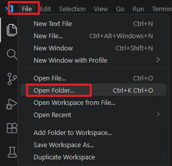
In VS Code, select File -> Open Folder... to open the root directory of this lesson's ESP-IDF project.
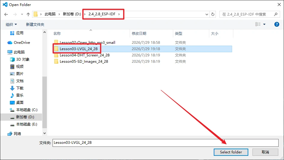
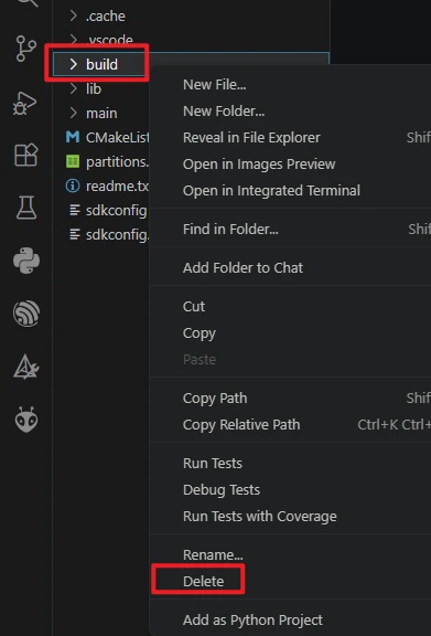
After opening the project, first run Build -> Delete to clear the build cache and path records left by the previous project. After switching computers, changing the ESP-IDF version, or copying the project, it is recommended to do this step first.
Confirm that VS Code has loaded ESP-IDF 5.5.4. If the version indicated in the status bar or the ESP-IDF extension is incorrect, return to the installation steps in Lesson 01 and reselect the 5.5.4 environment.

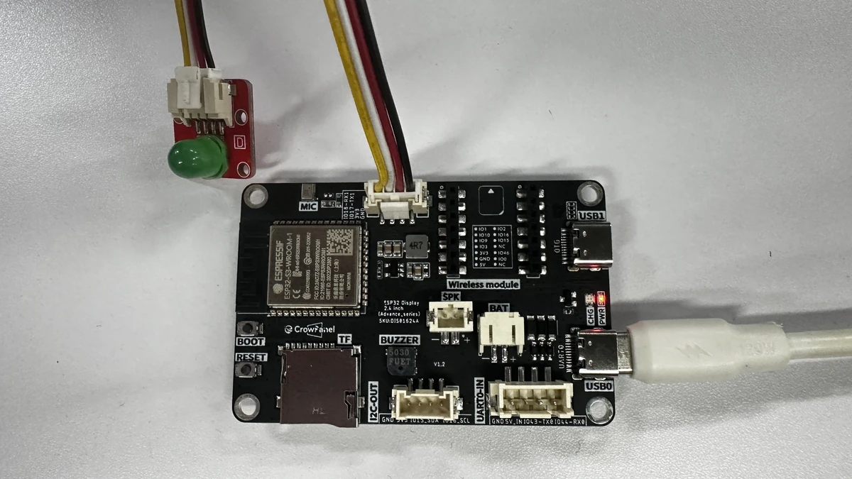
Connect the external LED, and use a USB cable that supports data transfer to connect the board to the computer.
Click the serial port location in the VS Code bottom status bar and select the actual COM port recognized by your computer.
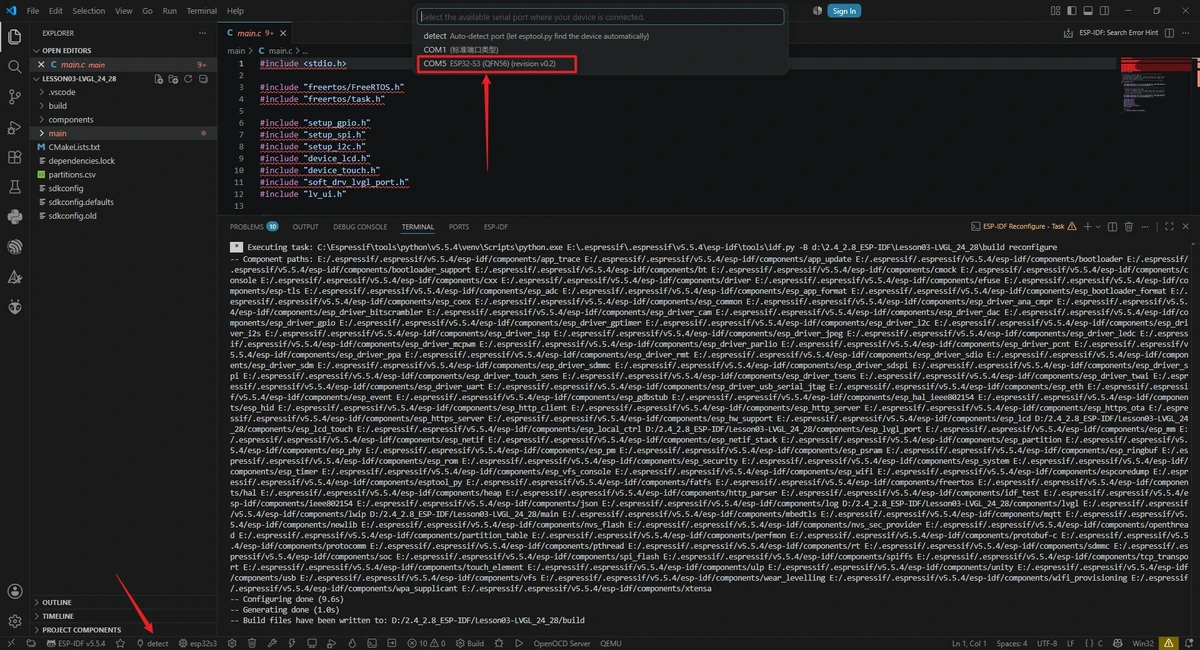
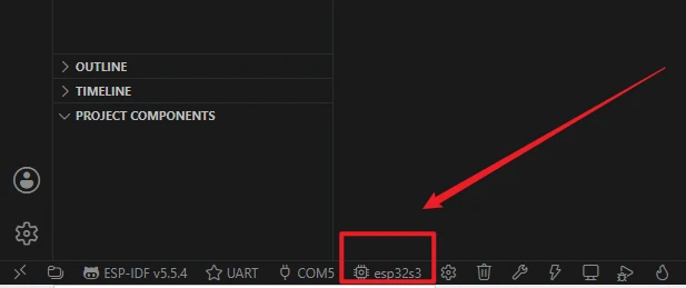
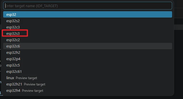
Click the target chip location in the status bar, or run the command ESP-IDF: Set Espressif Device Target, and select esp32s3 as the target chip. The reference image shows where to access this option; the actual selection should follow this lesson's esp32s3.
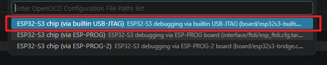
When selecting the debug configuration, choose one that matches the ESP32-S3 development board, such as the ESP32-S3 built-in USB-JTAG or the corresponding ESP32-S3 OpenOCD configuration. For ordinary UART flashing, the main requirements are a correctly set serial port and target chip.
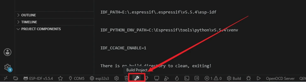
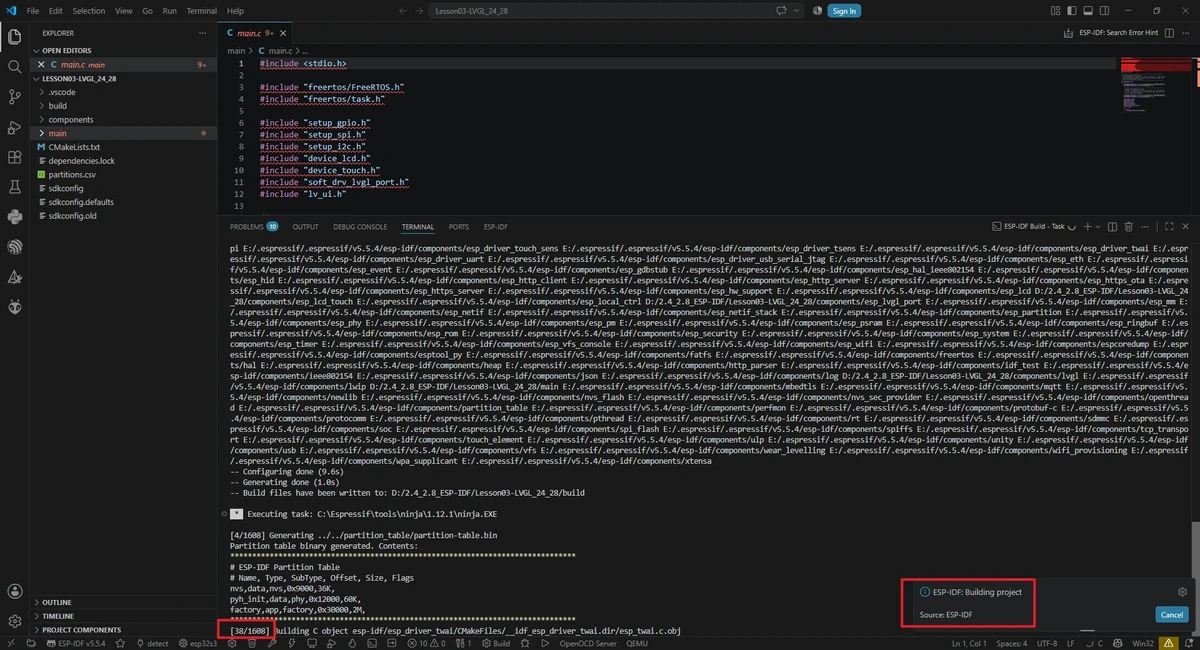
Click the Build button in the status bar to start compiling, or run the following in the ESP-IDF terminal:
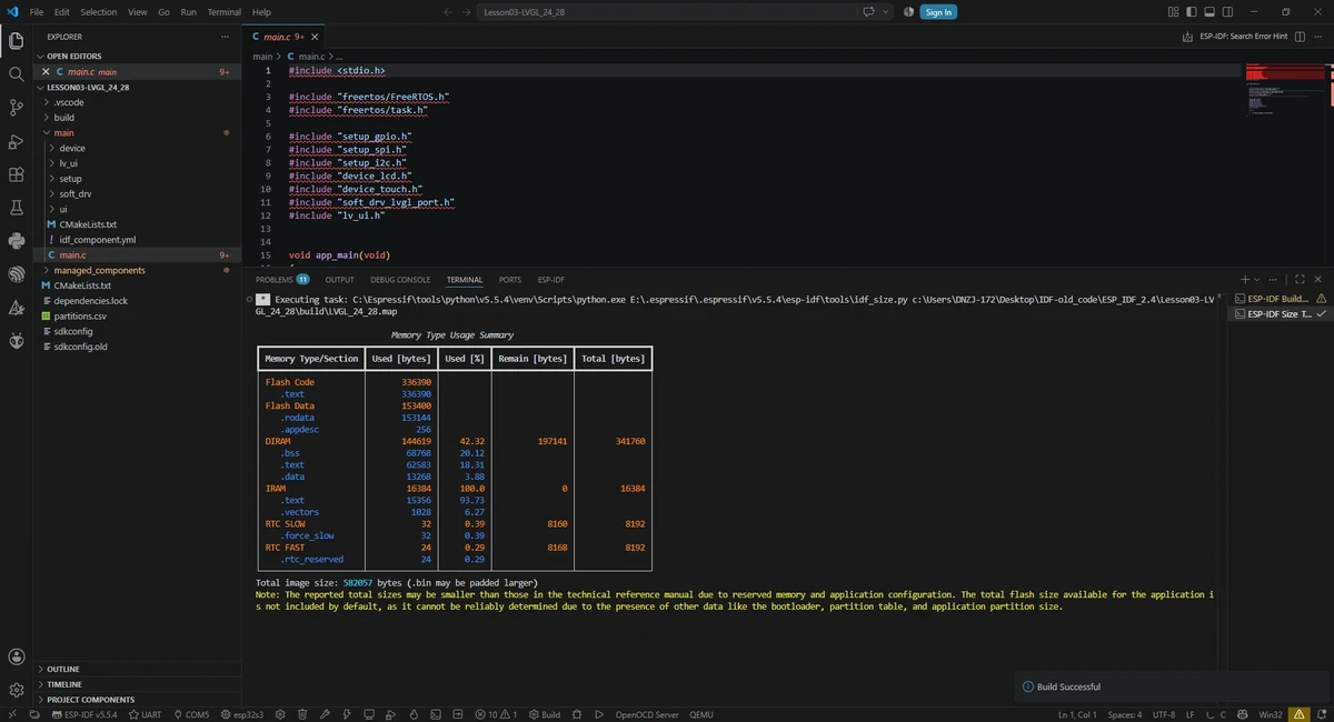
The first build needs to download and generate dependencies, so it will take longer; proceed to flashing only after you see the build success message.
Confirm that the flashing method is set to UART, then click the lightning icon Flash, or run the following in the ESP-IDF terminal:
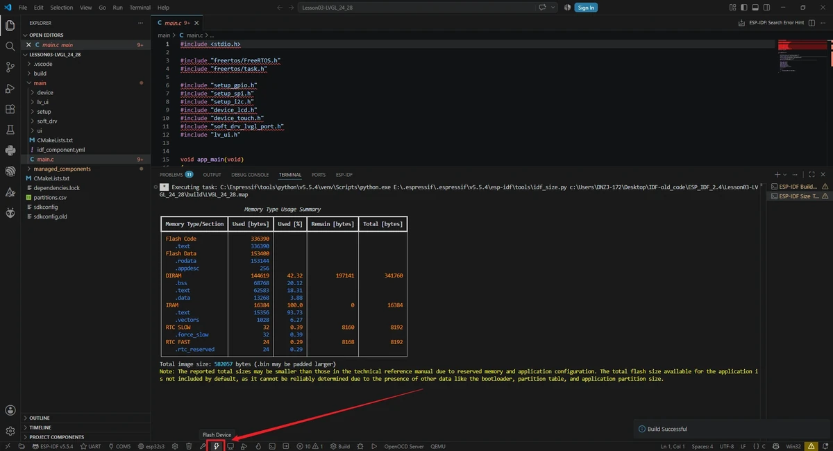
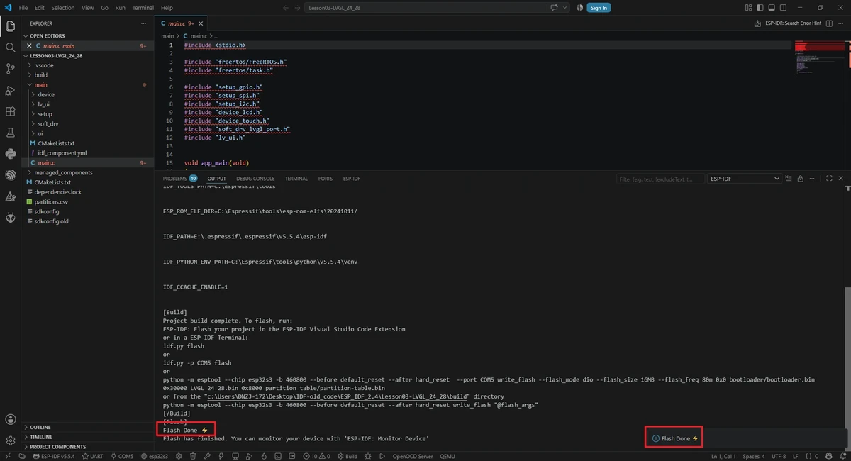
After flashing completes, click Monitor. Once the program starts, the screen will display the LVGL lamp control interface, and tapping the ON and OFF buttons controls the GPIO18 output state.

5. Hardware Operation Steps
Connect the external LED, and use a USB cable that supports data transfer to connect the board to the computer.
After flashing completes, wait for the board to reset; the screen should display the lamp control UI you just created. 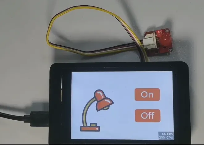
Tap the ON and Off buttons on the screen and observe whether the bulb/LED on the UART1 interface toggles on and off. 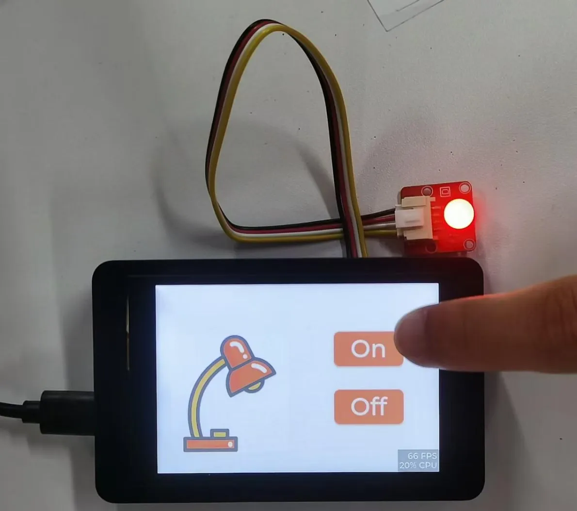
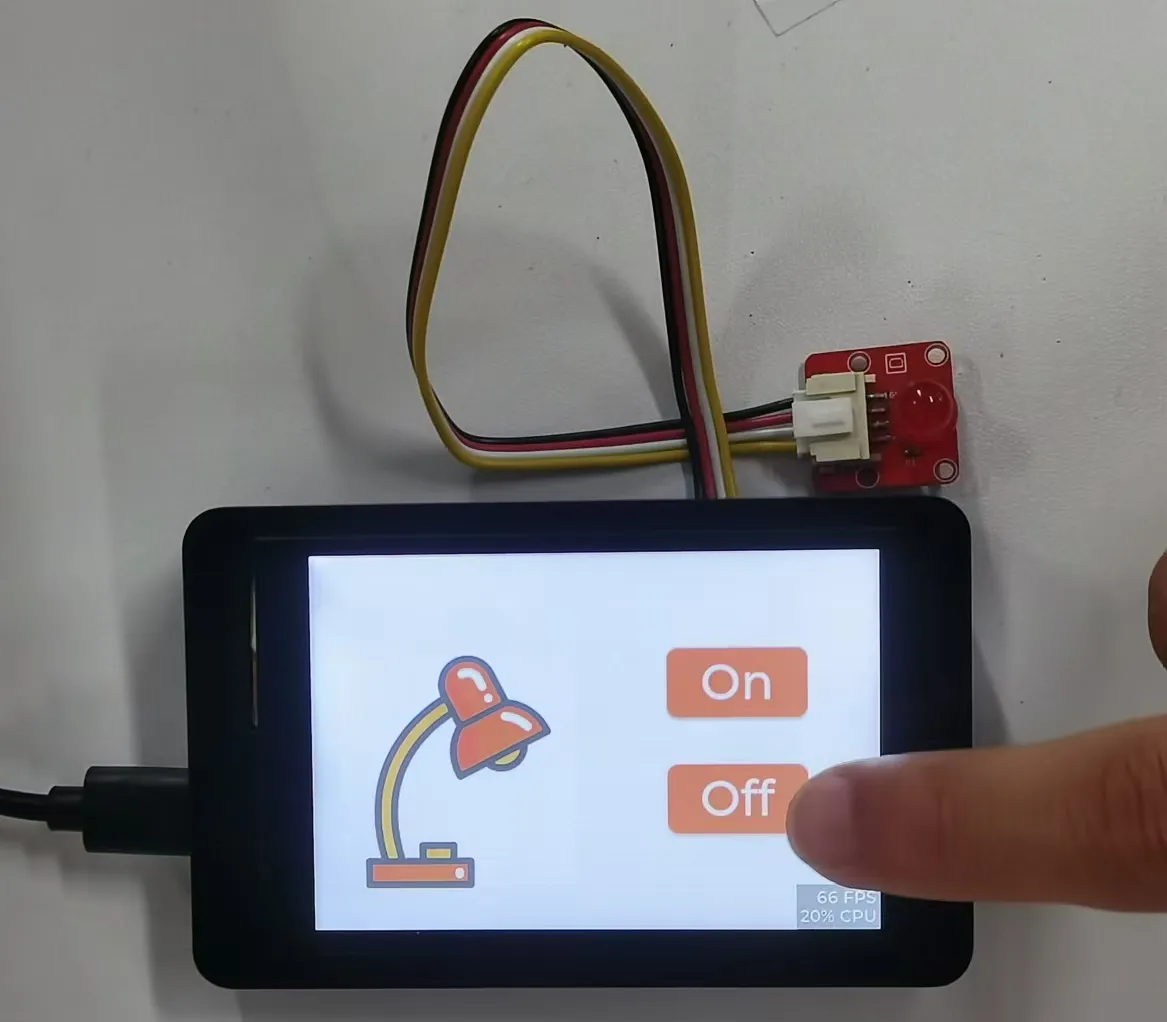
Note: GPIO18 is the primary control pin for the LVGL lamp control interface in this lesson. When troubleshooting the lamp control, first check the GPIO18 wiring, power supply, and UI event functions.
6. Key Code Explanation
The current code for this lesson is located in Lesson03-LVGL_24_28/main. In the upgraded project, the display, touch, and UI logic are no longer all written in a single file; instead, they are split into several layers: setup, device, soft_drv, lv_ui, and ui. The lower layer first initializes GPIO/SPI/I2C, then creates the LCD and touch devices, after which esp_lvgl_port registers the display and touch with LVGL, and finally the UI exported from SquareLine Studio is loaded.
6.1 Main Program Initialization Sequence
void app_main(void)
{
    gpio_set_direction(18, GPIO_MODE_OUTPUT);

    gpio_set_direction(GPIO_NUM_38, GPIO_MODE_OUTPUT);
    gpio_set_level(GPIO_NUM_38, 1);

    setup_gpio_init();
    setup_spi_init();
    setup_i2c_init();
    device_lcd_init();
    device_touch_init();
    soft_drv_lvgl_port_init();
    lv_ui_init();

    for(;;)
    {
        vTaskDelay(pdMS_TO_TICKS(100));
    }
}
GPIO18 is the lamp control output pin for this lesson and is configured as an output at the very start of the program. GPIO38 is used for enable/backlight-related control on the small-size screen, and is pulled high first to ensure the screen hardware is in a working state. The subsequent initialization order must not be changed arbitrarily: the LCD depends on the SPI bus, the touch depends on the I2C bus, the LVGL port depends on the already-created LCD/Touch handles, and the UI depends on the LVGL port having started.
6.2 GPIO, SPI, and I2C Initialization
setup_gpio.c is responsible for configuring the LCD backlight pin:
void setup_gpio_init(void)
{
    gpio_config_t gpio_cfg = {};
    gpio_cfg.mode = GPIO_MODE_OUTPUT;
    gpio_cfg.pin_bit_mask = 1ULL << LCD_BLK_NUM;
    gpio_cfg.pull_down_en = GPIO_PULLUP_DISABLE;
    gpio_cfg.pull_up_en = GPIO_PULLUP_DISABLE;
    gpio_cfg.intr_type = GPIO_INTR_DISABLE;
    ESP_ERROR_CHECK(gpio_config(&gpio_cfg));
}
setup_gpio.h defines the main pins for the screen and touch: the LCD uses SCLK=GPIO42, MOSI=GPIO39, DC=GPIO41, CS=GPIO40, backlight=GPIO5; the touch uses SDA=GPIO15, SCL=GPIO16, INT=GPIO47, RST=GPIO48.
void setup_spi_init(void)
{
    spi_bus_config_t spi_cfg = {};
    spi_cfg.sclk_io_num = LCD_SCLK_NUM;
    spi_cfg.mosi_io_num = LCD_MOSI_NUM;
    spi_cfg.miso_io_num = LCD_MISO_NUM;
    spi_cfg.quadwp_io_num = GPIO_NUM_NC;
    spi_cfg.quadhd_io_num = GPIO_NUM_NC;
    spi_cfg.max_transfer_sz = LCD_H_RES_DATA * LCD_BUFFER_H_DATA * sizeof(uint16_t);
    ESP_ERROR_CHECK(spi_bus_initialize(LCD_SPI2_HOST, &spi_cfg, SPI_DMA_CH_AUTO));
}
The SPI bus uses SPI2_HOST and enables SPI_DMA_CH_AUTO so that ESP-IDF automatically allocates a DMA channel. max_transfer_sz is set according to the size of a display buffer segment; later, when LVGL refreshes the screen, it sends RGB565 pixel data to the LCD over this SPI bus.
void setup_i2c_init(void)
{
    i2c_config_t i2c_cfg = {};
    i2c_cfg.mode = I2C_MODE_MASTER;
    i2c_cfg.scl_io_num = I2C_TOUCH_SCL;
    i2c_cfg.sda_io_num = I2C_TOUCH_SDA;
    i2c_cfg.sda_pullup_en = GPIO_PULLUP_ENABLE;
    i2c_cfg.scl_pullup_en = GPIO_PULLUP_ENABLE;
    i2c_cfg.master.clk_speed = 400000;
    ESP_ERROR_CHECK(i2c_param_config(I2C_TOUCH_PORT, &i2c_cfg));
    i2c_driver_install(I2C_TOUCH_PORT, i2c_cfg.mode, 0, 0, 0);
}
The touch chip communicates over I2C1 at a clock speed of 400 kHz. Only after the I2C driver is installed can the subsequent device_touch_init() create the touch device.
6.3 LCD Device Initialization
void device_lcd_init(void)
{
    esp_lcd_panel_io_spi_config_t io_config = {};
    io_config.dc_gpio_num = LCD_DC_NUM;
    io_config.cs_gpio_num = LCD_CS_NUM;
    io_config.pclk_hz = 40 * 1000 * 1000;
    io_config.lcd_cmd_bits = 8;
    io_config.lcd_param_bits = 8;
    io_config.spi_mode = 0;
    io_config.trans_queue_depth = 10;
    ESP_ERROR_CHECK(esp_lcd_new_panel_io_spi((esp_lcd_spi_bus_handle_t)LCD_SPI2_HOST, &io_config, &lcd_io));

    esp_lcd_panel_dev_config_t panel_config = {};
    panel_config.reset_gpio_num = LCD_RST_NUM;
    panel_config.color_space = ESP_LCD_COLOR_SPACE_RGB;
    panel_config.bits_per_pixel = 16;
    ESP_ERROR_CHECK(esp_lcd_new_panel_st7789(lcd_io, &panel_config, &lcd_panel));

    esp_lcd_panel_reset(lcd_panel);
    esp_lcd_panel_init(lcd_panel);
    esp_lcd_panel_set_gap(lcd_panel, 0, 0);
    esp_lcd_panel_invert_color(lcd_panel, true);
    esp_lcd_panel_disp_on_off(lcd_panel, true);
}
Here, lcd_io is first created based on the SPI bus, and then the ST7789 panel object lcd_panel is created. esp_lcd_panel_reset() and esp_lcd_panel_init() perform the screen reset and initialization; esp_lcd_panel_invert_color(..., true) matches the current screen's color display mode, and finally the display output is turned on.
6.4 Touch Device Initialization
void device_touch_init(void)
{
    esp_lcd_panel_io_i2c_config_t tp_io_config = ESP_LCD_TOUCH_IO_I2C_FT5x06_CONFIG();
    ESP_ERROR_CHECK(esp_lcd_new_panel_io_i2c((esp_lcd_i2c_bus_handle_t)I2C_TOUCH_PORT,
                                             &tp_io_config, &tp_io_handle));
    esp_lcd_touch_config_t tp_cfg = {};
    tp_cfg.x_max = LCD_V_RES;
    tp_cfg.y_max = LCD_H_RES;
    tp_cfg.rst_gpio_num = I2C_TOUCH_RST;
    tp_cfg.int_gpio_num = I2C_TOUCH_INT;
    tp_cfg.flags.swap_xy = 1;
    tp_cfg.flags.mirror_x = 0;
    tp_cfg.flags.mirror_y = 1;
    ESP_ERROR_CHECK(esp_lcd_touch_new_i2c_ft5x06(tp_io_handle, &tp_cfg, &tp));
}
The touch driver uses an FT5x06/FT6336U-compatible configuration, creates tp_io_handle over I2C, and then creates the tp touch handle. swap_xy and mirror_y are used to correct the touch coordinate orientation so that the finger tap position matches the screen display direction.
6.5 LVGL Port Registering Display and Touch
void soft_drv_lvgl_port_init(void)
{
    ESP_ERROR_CHECK(gpio_set_level(LCD_BLK_NUM, LCD_BL_NO_LEVEL));

    lvgl_port_cfg_t lvgl_cfg = {};
    lvgl_cfg.task_priority = 4;
    lvgl_cfg.task_stack = 4 * 1024;
    lvgl_cfg.task_affinity = -1;
    lvgl_cfg.task_max_sleep_ms = 500;
    lvgl_cfg.timer_period_ms = 5;
    ESP_ERROR_CHECK(lvgl_port_init(&lvgl_cfg));

    lvgl_port_display_cfg_t disp_cfg = {};
    disp_cfg.io_handle = lcd_io;
    disp_cfg.panel_handle = lcd_panel;
    disp_cfg.buffer_size = LCD_H_RES * LCD_DRAW_BUFF_HEIGHT;
    disp_cfg.double_buffer = LCD_DEAW_BUFF_DOUBLE;
    disp_cfg.hres = LCD_H_RES;
    disp_cfg.vres = LCD_V_RES;
    disp_cfg.color_format = LV_COLOR_FORMAT_RGB565;
    disp_cfg.rotation.swap_xy = true;
    disp_cfg.rotation.mirror_x = false;
    disp_cfg.rotation.mirror_y = true;
    disp_cfg.flags.buff_dma = true;
    disp_cfg.flags.swap_bytes = true;
    lvgl_disp = lvgl_port_add_disp(&disp_cfg);

    lvgl_port_touch_cfg_t touch_cfg = {};
    touch_cfg.disp = lvgl_disp;
    touch_cfg.handle = tp;
    lvgl_touch_indev = lvgl_port_add_touch(&touch_cfg);
}
esp_lvgl_port creates the LVGL background task and is responsible for periodically calling the LVGL timers. The display configuration specifies the LCD handle, resolution, buffer, RGB565 color format, rotation direction, and DMA screen refresh; the touch configuration binds the tp handle to the current display object. Only after this step can LVGL draw the interface onto the screen and receive touch clicks.
6.6 Loading the UI Exported from SquareLine Studio
ui_init() is located in main/ui/ui.c and is generated by SquareLine Studio. It creates the default theme, initializes ui_Screen1, and loads the screen via lv_disp_load_scr(ui_Screen1). Because LVGL objects are maintained by the background task, creating or modifying UI objects requires wrapping the operations with lvgl_port_lock() / lvgl_port_unlock() to prevent multiple tasks from accessing LVGL at the same time.
6.7 Button Events to Control GPIO18
void ui_event_Button1(lv_event_t * e)
{
    lv_event_code_t event_code = lv_event_get_code(e);

    if(event_code == LV_EVENT_RELEASED) {
        Lamp_on(e);
    }
}

void ui_event_Button2(lv_event_t * e)
{
    lv_event_code_t event_code = lv_event_get_code(e);

    if(event_code == LV_EVENT_RELEASED) {
        Lamp_off(e);
    }
}
The button callbacks generated by SquareLine only check the event type. When the button is released, Button1 calls Lamp_on() and Button2 calls Lamp_off().
void Lamp_on(lv_event_t * e)
{
    printf("open led\n");
    gpio_set_level(18, 1);
}

void Lamp_off(lv_event_t * e)
{
    printf("close led\n");
    gpio_set_level(18, 0);
}
The actual hardware control is handled by gpio_set_level() in ui_events.c. A high logic level on GPIO18 turns on the external LED, while a low logic level turns it off. If the interface responds to touches but the LED does not light up, check whether ui_events.c is included in the project, whether the GPIO18 wiring is correct, and whether the external LED module has reliable power and GND connections.
6.8 Main Task Keeps Running
After initialization, LVGL refresh and touch handling are mainly maintained by the background task created by esp_lvgl_port. app_main() cannot return directly, so this FreeRTOS delay loop keeps the main task alive without occupying the CPU for extended periods.
7. UI Production Steps
The UI in this section is created using SquareLine Studio. The official workflow is to first create a TFT_eSPI-compatible UI project in SquareLine Studio, then add the light bulb image, an On button, and an Off button, bind the Lamp_on and Lamp_off callback functions to the two buttons respectively, and finally export the UI files for the ESP-IDF project.
For downloading and basic installation of SquareLine Studio, refer to:
7.1 Creating a SquareLine Project
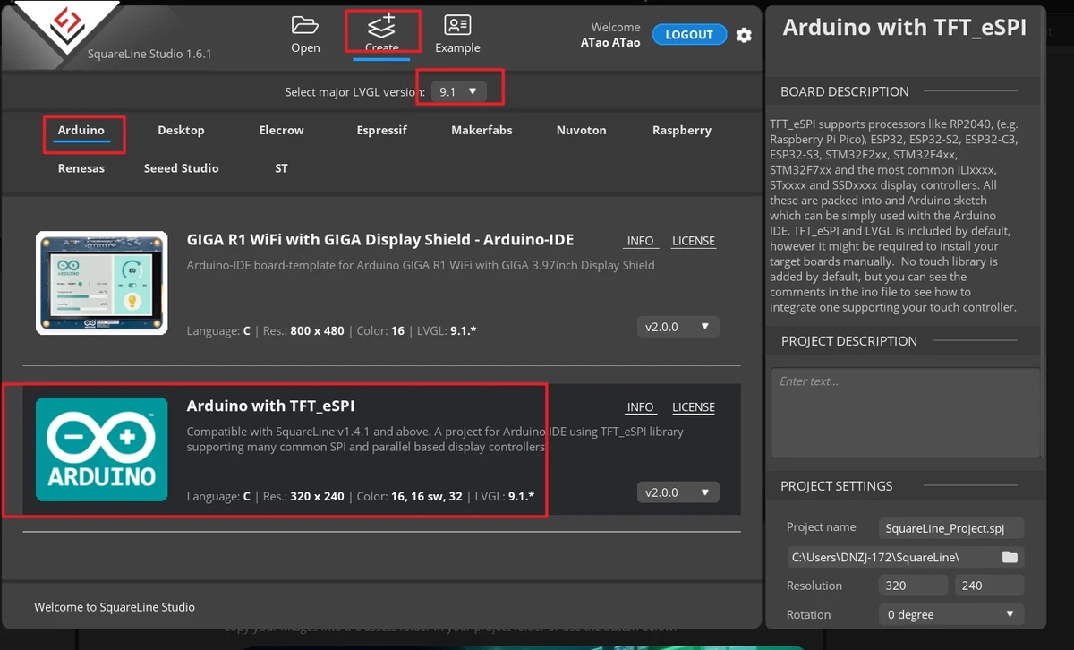
Open SquareLine Studio and click Create at the top. When creating a new project, you must select LVGL 9.1.0.
In the board category, select the TFT_eSPI-compatible template category shown by SquareLine Studio.
Select the TFT_eSPI project template.
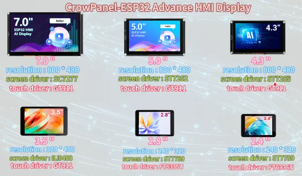
Confirm the resolution based on the screen size. The course projects for 2.4-inch and 2.8-inch displays use 320 x 240.
In the Project Settings on the right, set the project name and path, and confirm the key parameters:
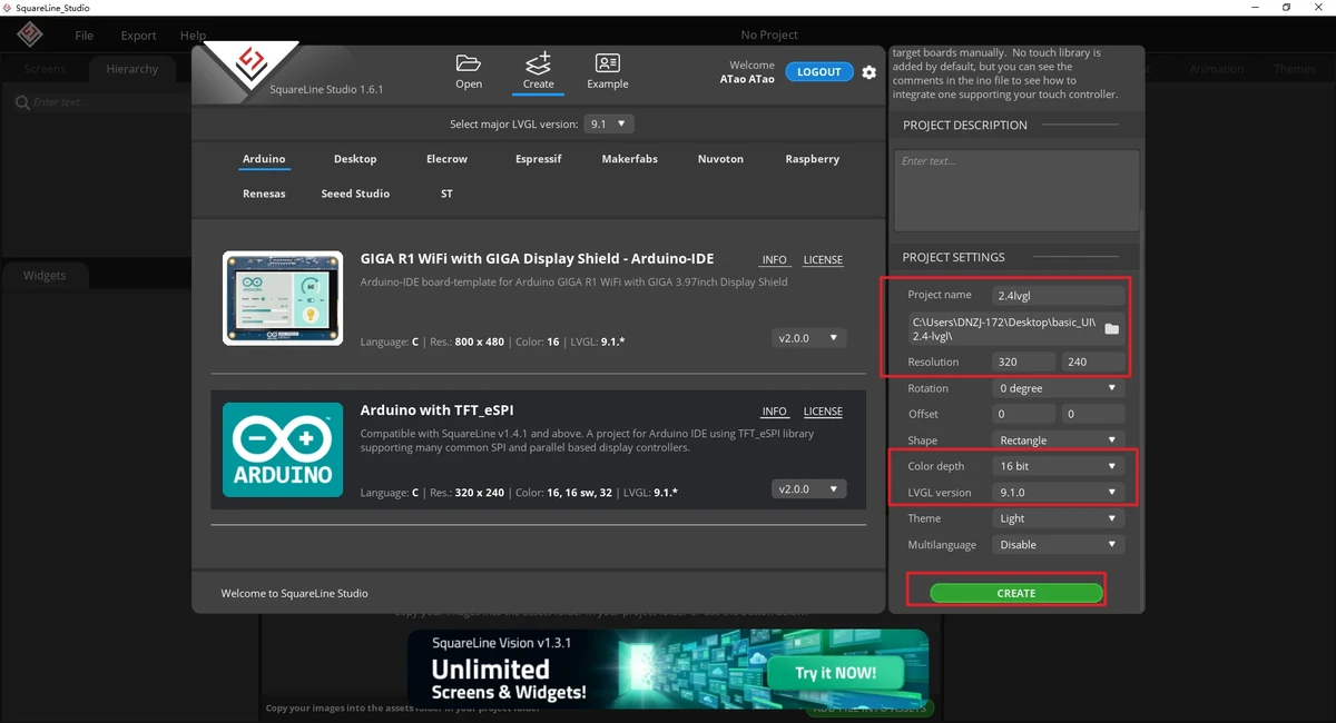
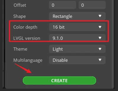
After confirming the parameters, click CREATE to create the project.
7.2 Importing the Light Bulb Image Asset
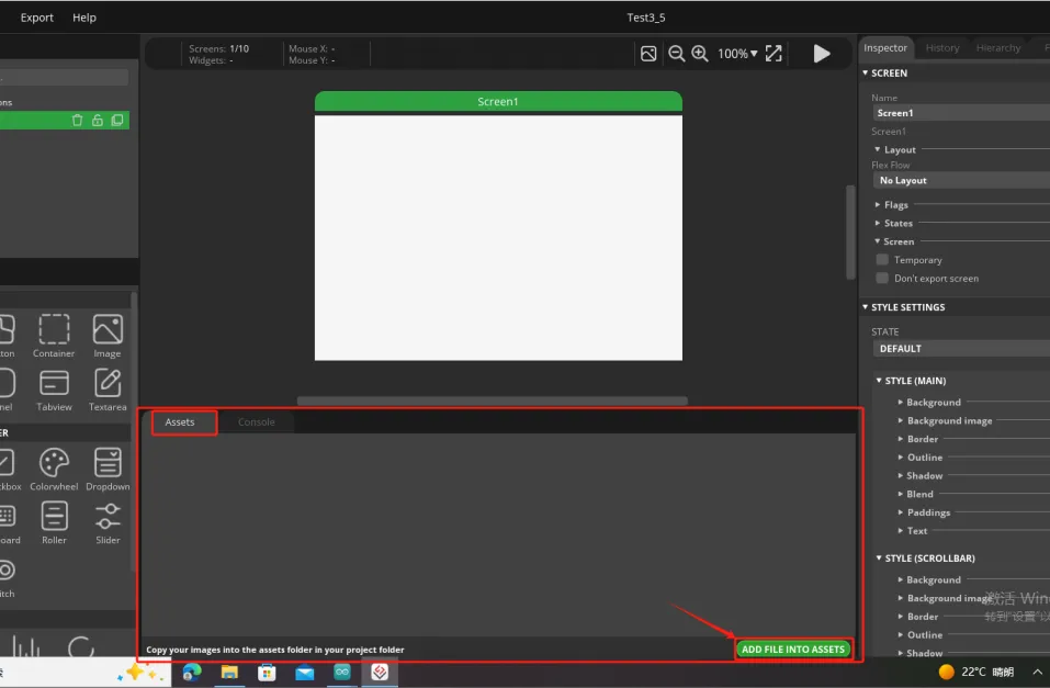
After entering the project editing interface, switch to the Assets area at the bottom.
Click ADD FILE INTO ASSETS to import the light bulb image asset into the project resources.
Image asset download link: lamp_28.png
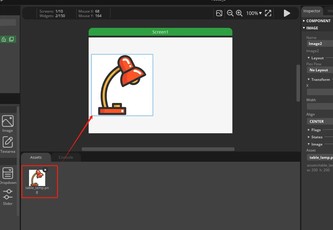
After importing, drag the light bulb image asset onto the Screen1 canvas. Adjust the image position on the canvas so it sits on the left side of the screen, leaving space for the button area on the right.
7.3 Adding the On Button
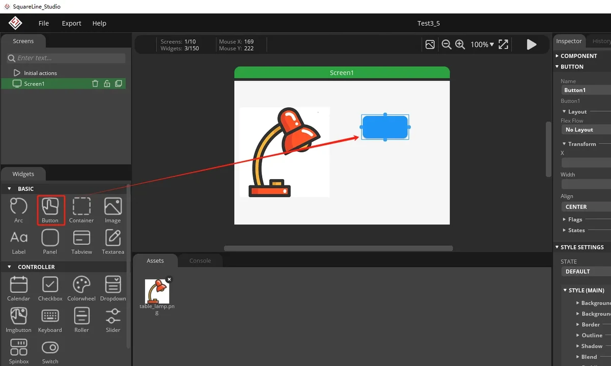
In the left Widgets > BASIC, select Button.
Drag the Button onto the right side of the canvas as the On button.
Select the button and adjust its position and size in the Inspector on the right.
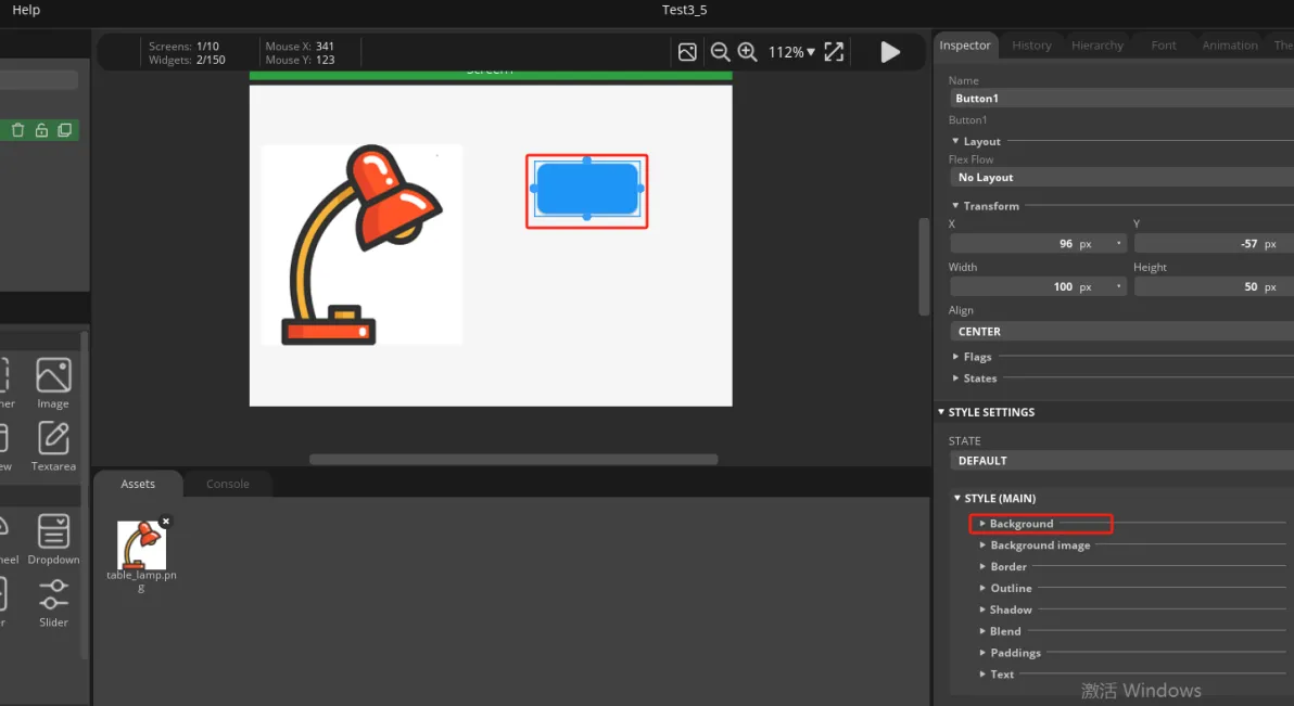
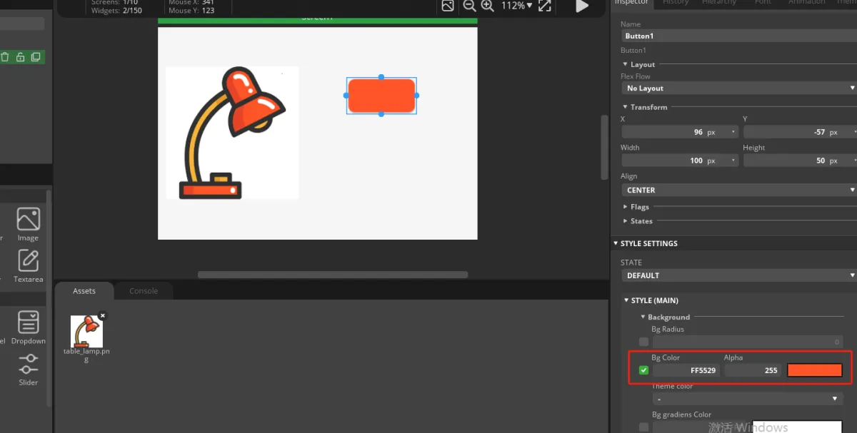
Expand STYLE (MAIN) > Background and set the button background color to orange-red. The official example color is FF5529.
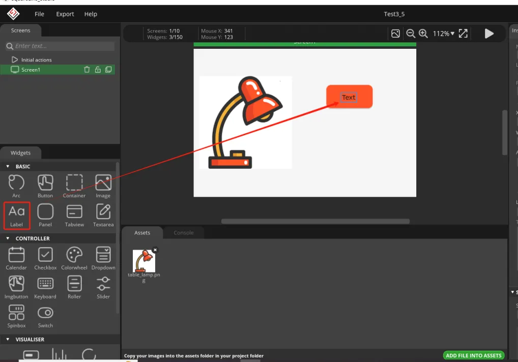
Add a Label from the left Widgets > BASIC and drag it into the button.
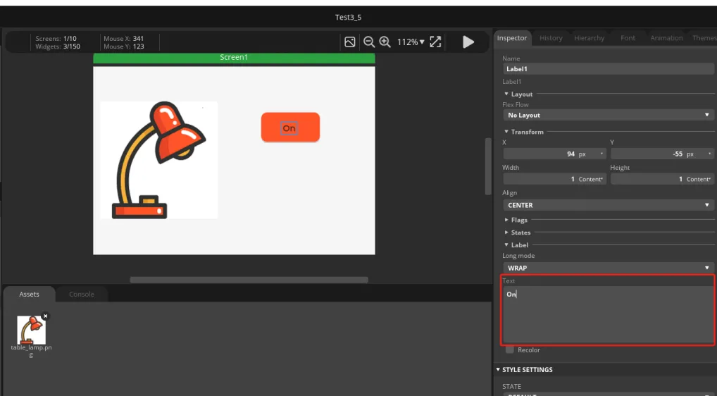
Select the Label and change its text to On in the text box on the right.
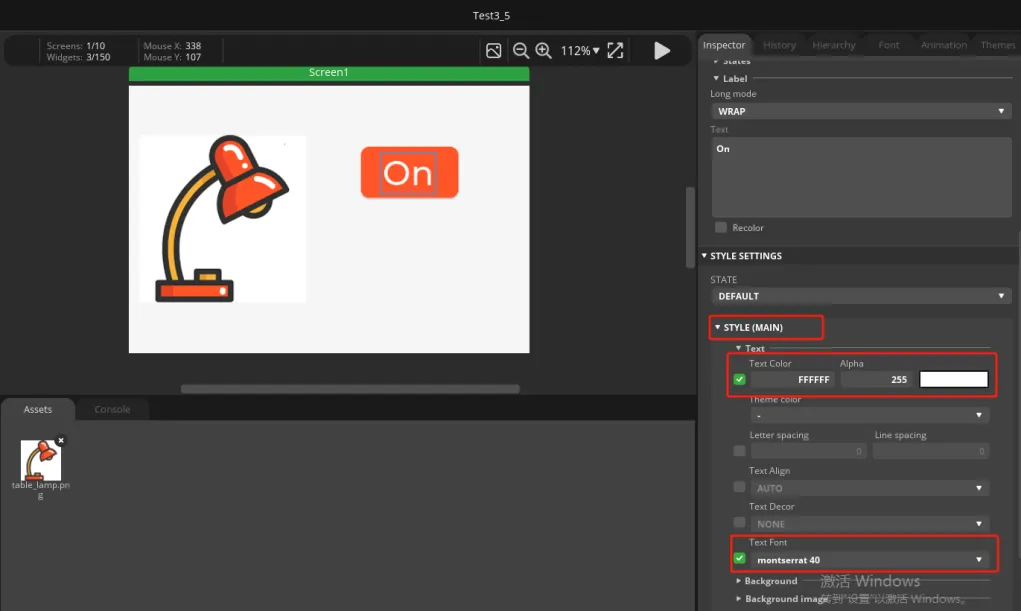
Adjust the Label style, set the text color to white, and choose an appropriate font size. Here, montserrat 40 is used.
In the Hierarchy panel on the right, confirm that the Label is a child of the Button.
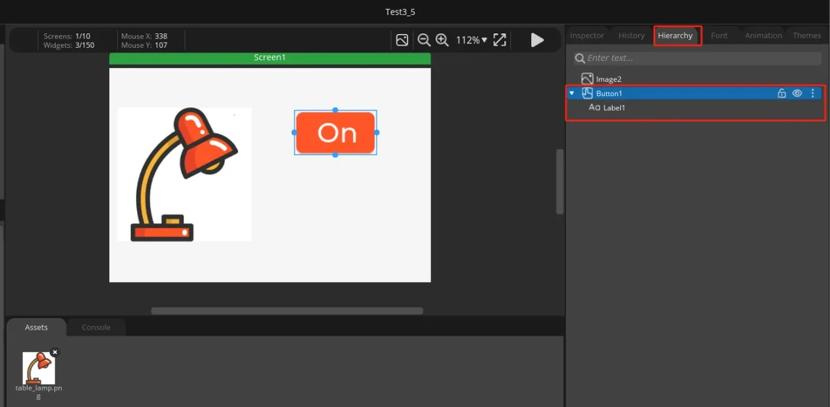
7.4 Copying and Creating the Off Button
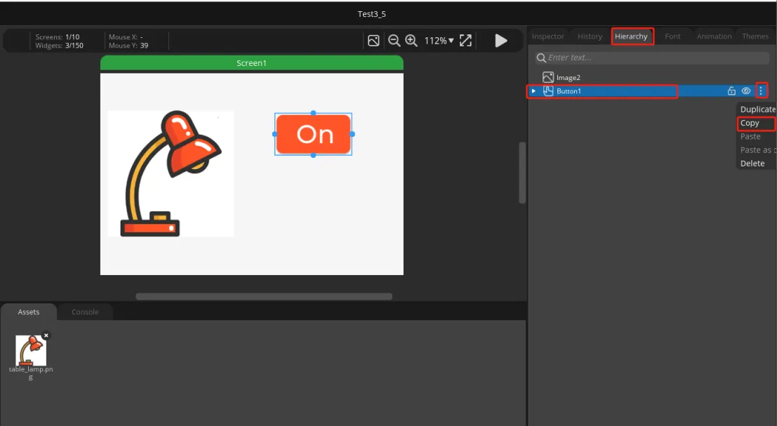
In the Hierarchy panel, select the finished Button1.
Open the more menu and select Copy.
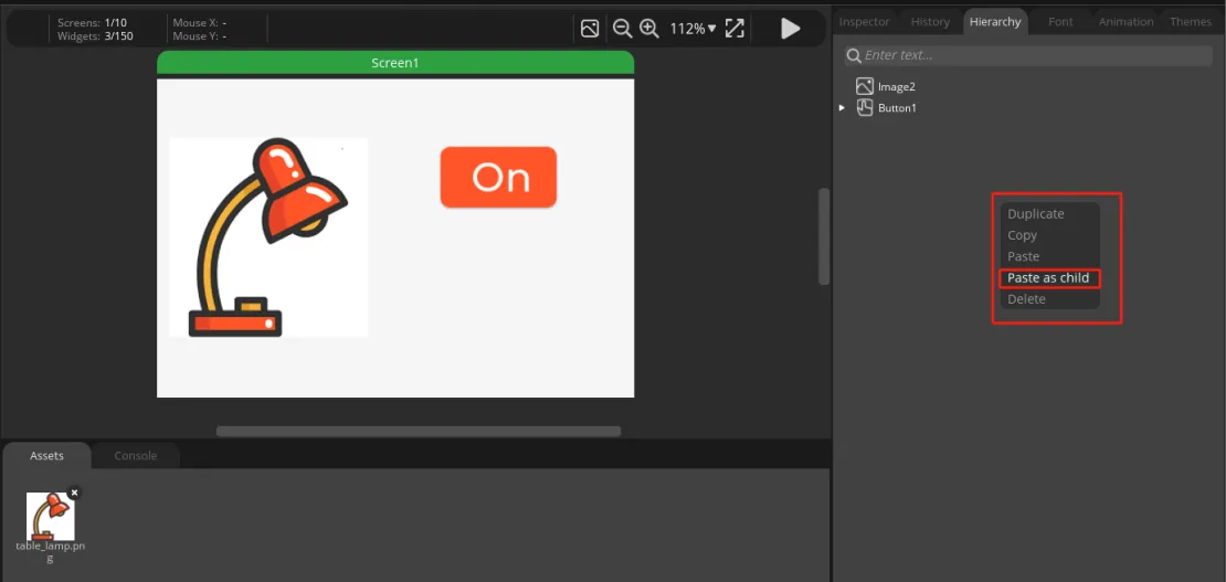
Paste it as a new button on the canvas or in the hierarchy. Use Paste as child to complete the copy.
Move the copied button below the On button.
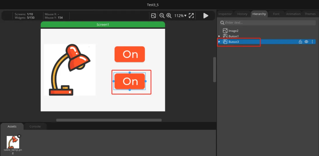
Select the Label in the new button and change its text to Off.
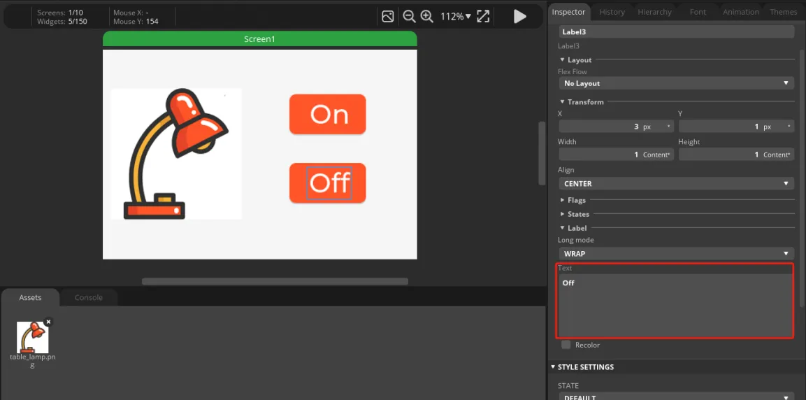
Adjust the position and background color of the two buttons as needed so that the On / Off buttons are arranged vertically on the right side.
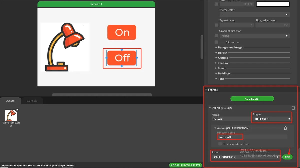
7.5 Setting Button Events
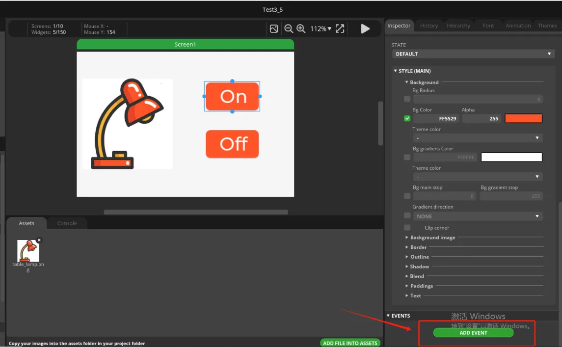
Select the On button and scroll the Inspector on the right to the EVENTS area.
Click ADD EVENT to add an event.
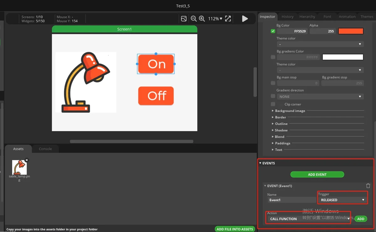
Set Trigger to RELEASED.
Set Action to CALL FUNCTION.
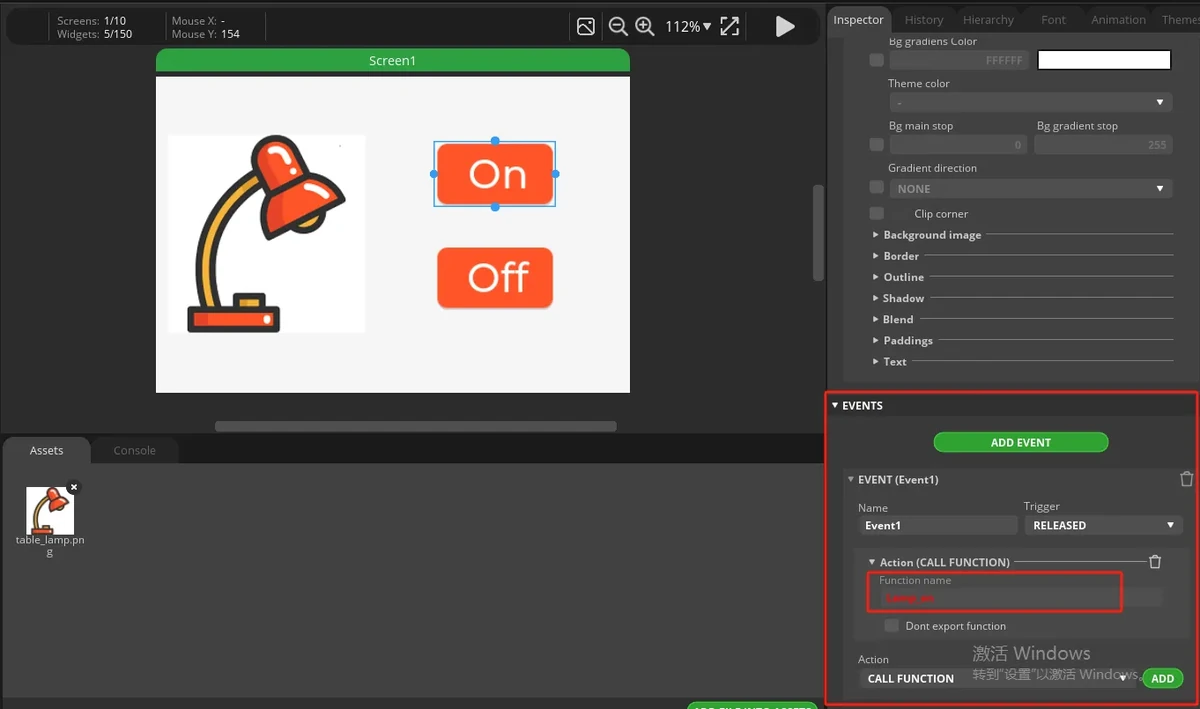
Enter the Function name:
Select the Off button and add an event the same way.
Set Trigger to RELEASED, set Action to CALL FUNCTION, and enter the Function name:
Note: The function name for Call function must match the function name in the exported UI project exactly. In this lesson, the ON button uses Lamp_on and the Off button uses Lamp_off. A capitalization error will prevent the button from turning on the LED.
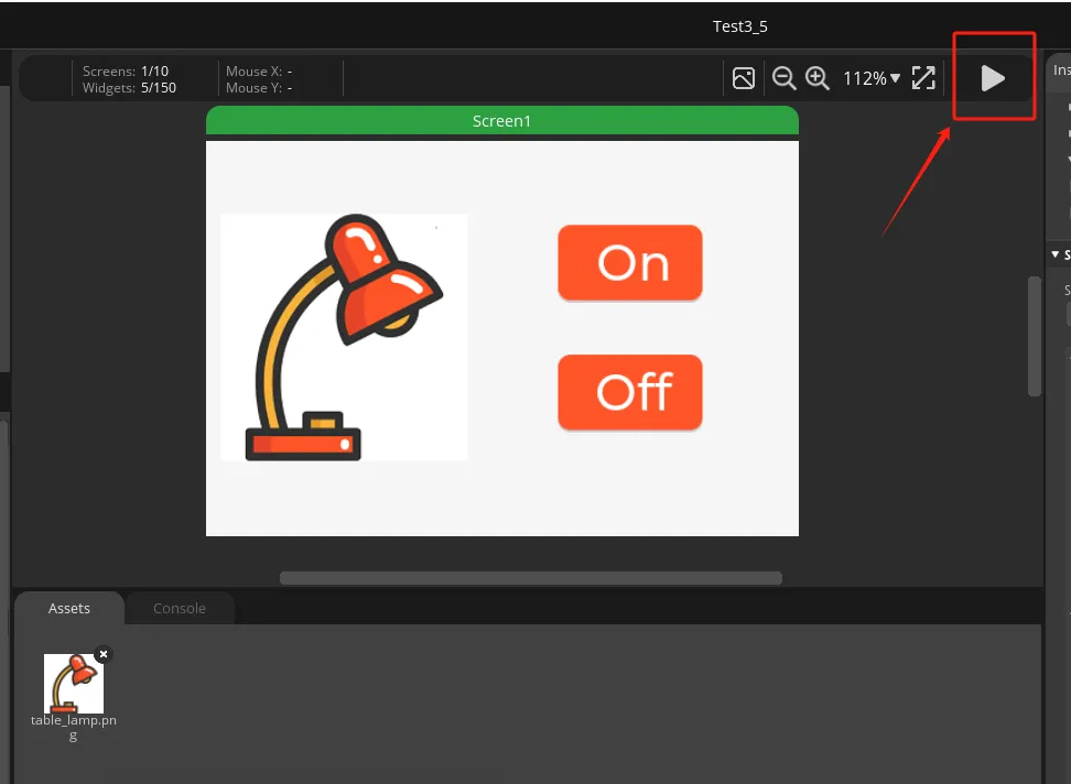
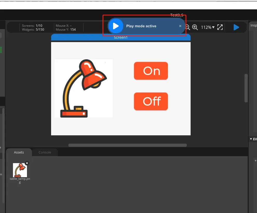
Click the play button in the top-right corner to enter preview mode. After adding the events, run the program and check whether the On / Off buttons respond to clicks normally.
7.6 Setting the Export Path
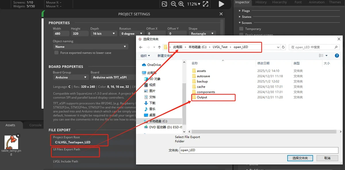
Click File > Project Settings to open the project settings.
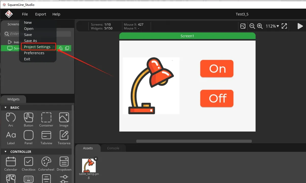
In FILE EXPORT, set the export path. In the example, Project Export Root points to the SquareLine project directory, and UI Files Export Path points to the Output folder.
Set LVGL Include Path to:
Check Flat export (exports all files to one folder), then click APPLY CHANGES.
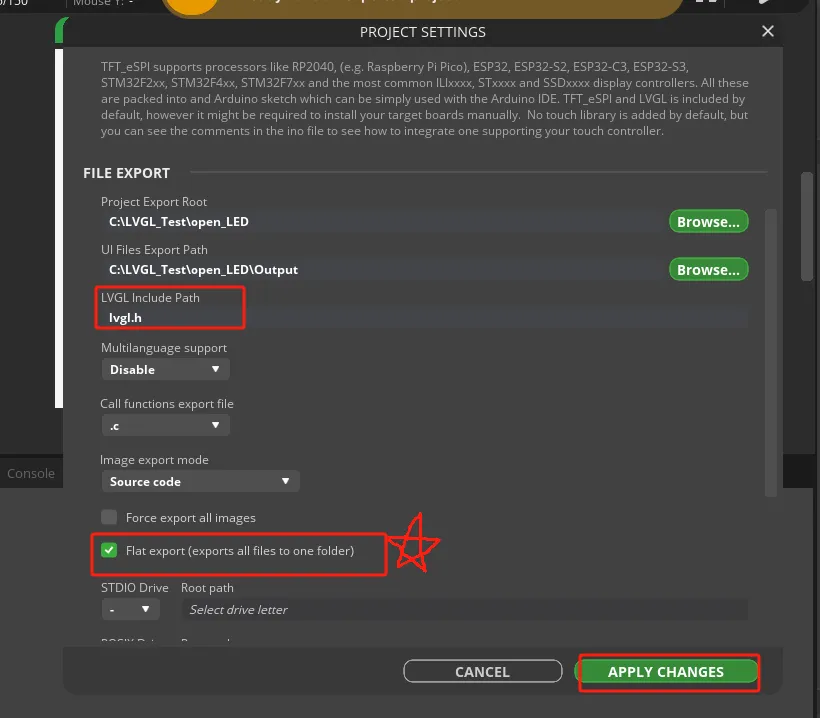
Note: It is recommended to check Flat export so that the exported UI files are consolidated into a single folder, making it less likely to miss files when copying them into the ESP-IDF project later.
7.7 Exporting the UI Files and Copying Them to the ESP-IDF Project
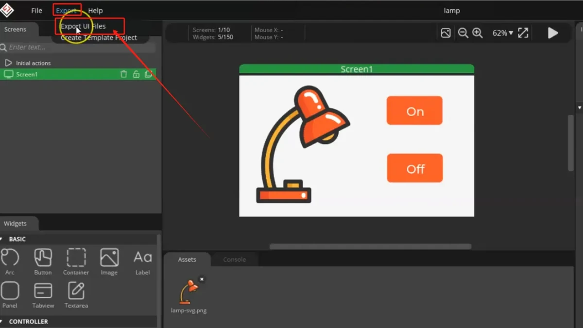
Click Export > Export UI Files in the top menu.
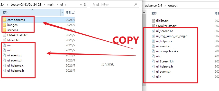
Open the exported Output folder and confirm that it contains the UI source files, event files, helper files, and image resource files. Common files include:
ui.c
ui.h
ui_events.c
ui_events.h
ui_helpers.c
ui_helpers.h
ui_Screen1.c
ui_comp_hook.c
ui_img_lamp_28_png.c
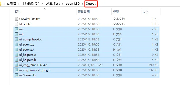
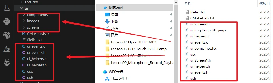
Copy the exported UI files into the ESP-IDF project directory 2.4_2.8_LVGL
Note: The 2.4-inch / 2.8-inch displays must use a resolution of 320 x 240; if you mistakenly select 480 x 320 or 800 x 480, the exported UI coordinates and image sizes will not match the screen.
8. Experimental Result
Click the ON and Off buttons on the screen and observe whether the light bulb/LED on the UART1 interface toggles on and off.
9. Code Download
Code download link: Lesson03-LVGL_24_28
Image asset download link: lamp_28.png