3.5inch_Lesson04_DHT20_LVGL
1. Course Introduction
This lesson reads the DHT20 temperature and humidity sensor within an ESP-IDF project and writes the data into an LVGL label. The display and touch portions reuse the LovyanGFX + LVGL structure from Lesson03. The new content covers I2C sensor initialization, periodic reading, and label refreshing.
Reference materials:
2. Learning Objectives
- Be able to open and compile the
Lesson04_DHT_Screen_35project. - Be able to connect the DHT20 temperature and humidity sensor and verify the I2C pins.
- Be able to use SquareLine Studio to create a
480 x 320temperature and humidity display interface. - Be able to explain how the DHT20 readings are written into
ui_TempLabel1andui_HumiLabel2. - Be able to troubleshoot when the display does not refresh, readings are abnormal, or the UI is misaligned.
3. What You Need to Prepare
- Hardware: CrowPanel Advance 3.5inch ESP32-S3 development board, DHT20 temperature and humidity sensor.
- Software: VS Code, ESP-IDF extension, SquareLine Studio.
- Project:
Lesson04_DHT_Screen_35 - Key files:
main/main.cpp,main/LovyanGFX_Driver.h,main/ui*.c,main/ui*.h. - Dependencies:
lib/Crowbits_DHT20/inside the project, LVGL, LovyanGFX. - UI size:
480 x 320.
Code and Resource Download
Code download: - Lesson04-DHT_Screen_35
Resource download: - 480x320/background.png

4. ESP-IDF Software Operation Steps
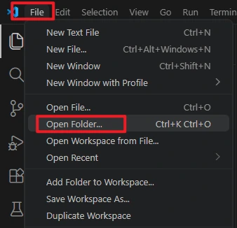
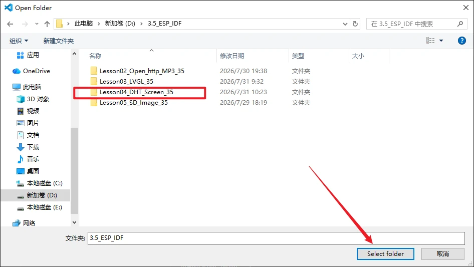
Open this lesson's project directory in VS Code.
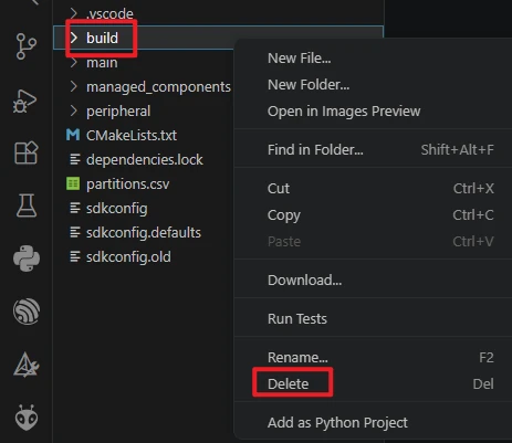
After opening the project, first run Build -> Delete to clear the build cache and path records generated by the old project. After switching computers, changing the ESP-IDF version, or copying the project, it is recommended to do this step first.
Confirm that VS Code has loaded ESP-IDF 5.5.4. If the version shown in the status bar or the ESP-IDF extension prompt is incorrect, go back to the installation steps in Lesson01 and reselect the 5.5.4 environment.

Connect the DHT20 to the I2C interface, and use a USB cable that supports data transmission to connect the development board to the computer.
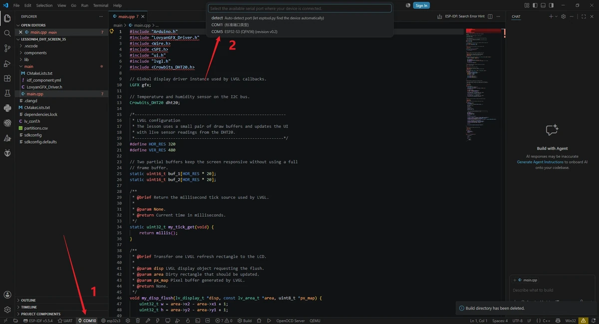
Click the serial port location in the VS Code bottom status bar, and select the actual COM port recognized by the computer.
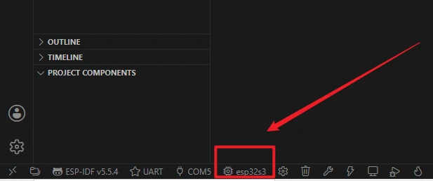
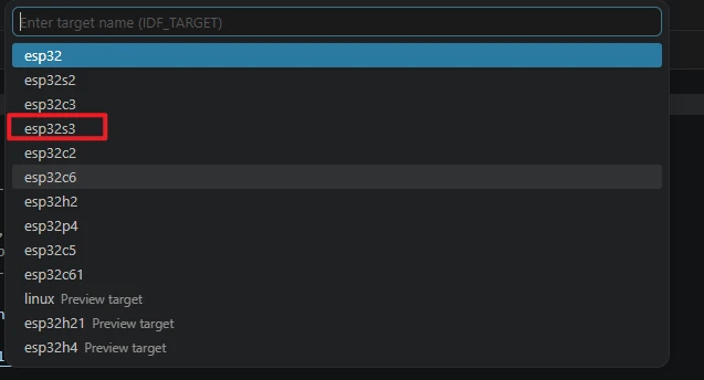
Click the target chip location in the status bar, or run the command ESP-IDF: Set Espressif Device Target, and select esp32s3 as the target chip. The reference image is provided to illustrate the entry point; the actual selection should follow this course's esp32s3.
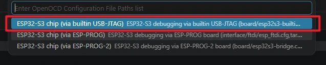
When selecting the debug configuration, choose the configuration that matches the ESP32-S3 development board, such as the ESP32-S3 built-in USB-JTAG or the corresponding ESP32-S3 OpenOCD configuration. Ordinary UART flashing mainly depends on the serial port and the target chip being set correctly.
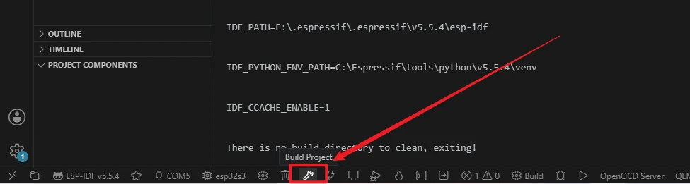
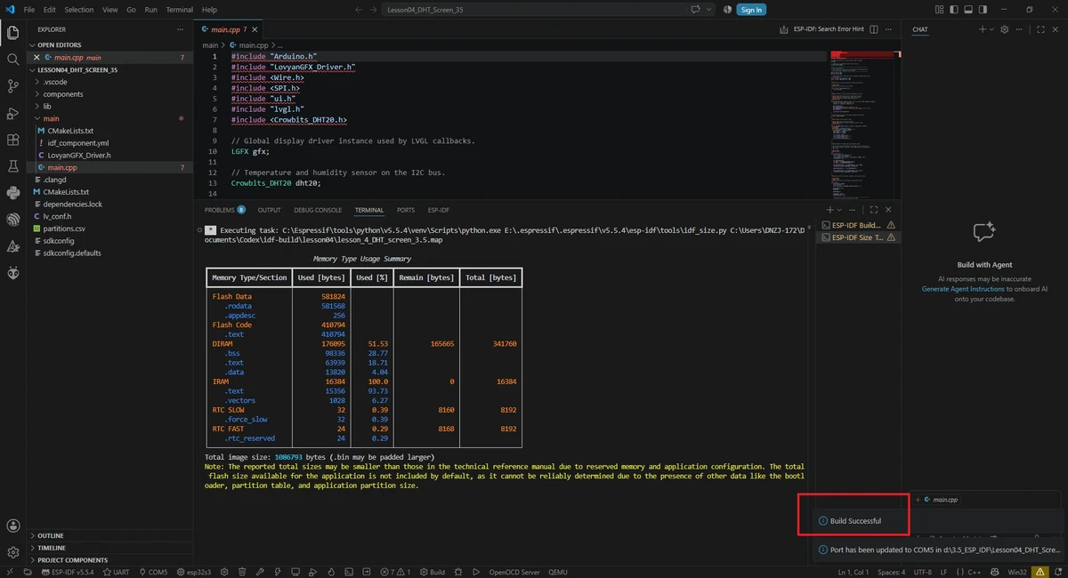
Click the Build button in the status bar to start compiling, or run in the ESP-IDF terminal:
The first compilation needs to download and generate dependencies, so it will take a relatively long time; continue flashing only after seeing the build success message.

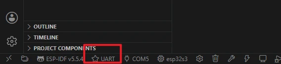
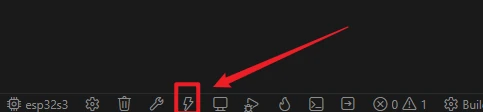
Confirm the flashing method is UART, then click the lightning icon Flash, or run in the ESP-IDF terminal:
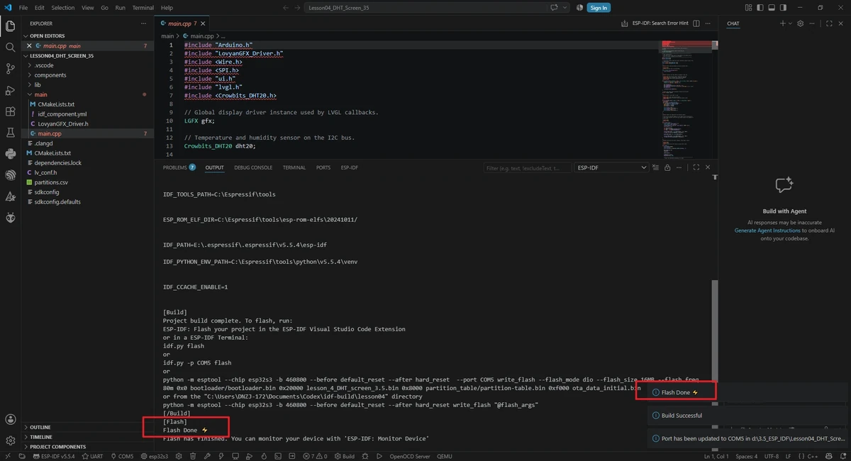
5. Hardware Operation Steps
-
Connect the DHT20 module.
-
The DHT20 uses I2C communication; in the project, SDA is GPIO15 and SCL is GPIO16.
-
Use a USB data cable to connect the development board and flash the program.
-
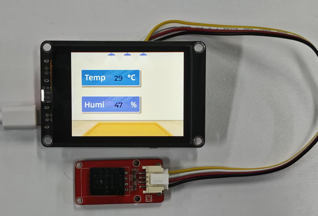
After flashing is complete, observe the temperature and humidity values on the screen.
-
Bring your hand close to or gently blow on the sensor, and observe the changes in the temperature and humidity values.
6. Key Code Explanation
6.1 DHT20 Initialization
First start the I2C bus, then initialize the DHT20. If the sensor does not respond, first check whether SDA/SCL are reversed, whether the power supply is stable, and whether the sensor module address is compatible.
6.2 Periodic Sensor Reading
static uint32_t last_read_ms = 0;
const uint32_t now = millis();
if(last_read_ms != 0 && now - last_read_ms < 2000) return;
last_read_ms = now;
The program limits temperature and humidity updates to once every 2 seconds, avoiding accessing the sensor and refreshing the UI on every loop() call. DHT20 readings do not require millisecond-level refresh; reading too frequently is instead unfavorable for observing stable data.
6.3 Writing Data to LVGL Labels
char DHT_buffer[6];
int temp = (int)dht20.getTemperature();
int humi = (int)dht20.getHumidity();

snprintf(DHT_buffer, sizeof(DHT_buffer), "%d", temp);
lv_label_set_text(ui_TempLabel1, DHT_buffer);

memset(DHT_buffer, 0, sizeof(DHT_buffer));

snprintf(DHT_buffer, sizeof(DHT_buffer), "%d", humi);
lv_label_set_text(ui_HumiLabel2, DHT_buffer);
The code converts the floating-point readings into integers, then writes them into the two labels. If serial debugging confirms the sensor has data but the screen does not refresh, focus on checking whether the control names exported by SquareLine are still TempLabel1 and HumiLabel2.
6.4 LVGL Refresh and Touch
lv_display_set_buffers(display, buf_1, buf_2, sizeof(buf_1), LV_DISPLAY_RENDER_MODE_PARTIAL);
lv_indev_set_read_cb(touch_indev, my_touchpad_read);
Although this lesson mainly displays temperature and humidity, it still registers touch input. When the display is abnormal, first check the display callback and the 480 x 320 size; when the touch log is abnormal, then check the GT911 I2C and mapping.
7. UI Resource Creation Process
Next, the following uses an externally connected temperature and humidity sensor on the I2C-OUT interface as an example. To make the experimental phenomenon more intuitive, this section uses LVGL to create an interface that displays temperature and humidity. The UI creation process for this lesson must use a 480 × 320 canvas and a 480x320 background image.
For SquareLine Studio download and installation methods, refer to: https://www.elecrow.com/wiki/Create_LVGL_UI_with_SquareLine_Studio.html
Open SquareLine Studio.
After launching SquareLine Studio, enter the main interface. If the software is not yet installed, first refer to Lesson03 or the link above to complete the installation. This section uses it to generate the LVGL ui.c, ui.h, image resources, and control object files.
Create a SquareLine Studio UI project template.
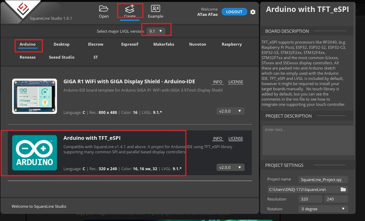
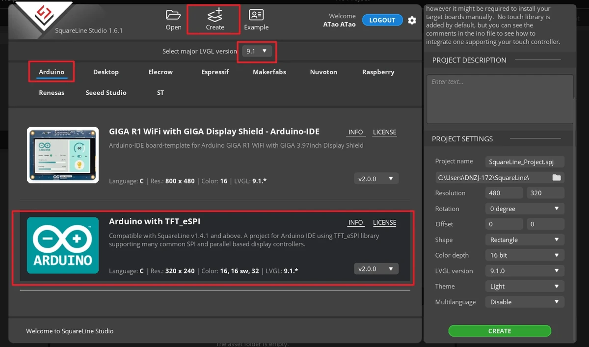
In the welcome screen, first click Create at the top. When creating a new project, you must select LVGL 9.1.0. Then select the TFT_eSPI-compatible category on the left, and choose the TFT_eSPI template in the middle. This template generates UI files that will be copied into the ESP-IDF project.
Note: When selecting this framework template, SquareLine Studio generates template code suitable for TFT_eSPI. SquareLine Studio also supports other graphics libraries; when switching to other hardware, you need to modify the display code according to the actual library.
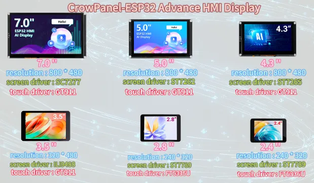
Confirm the resolution based on the screen size. The 3.5inch course project uses 480 × 320.
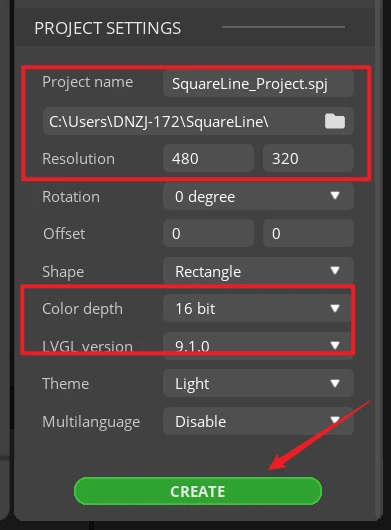
In the Project Settings on the right, set the project name and path, and confirm the key parameters:
After confirming the parameters, click CREATE to create the project.
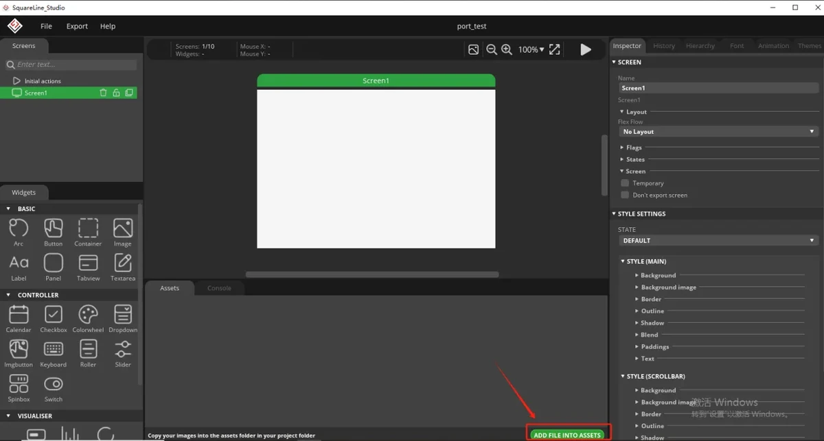
Prepare the background image resource provided by the course.
This lesson uses lesson-05/source material/480x320/background.png. The image assets can be downloaded from the 3.5-inch repository asset path: 480x320/background.png.
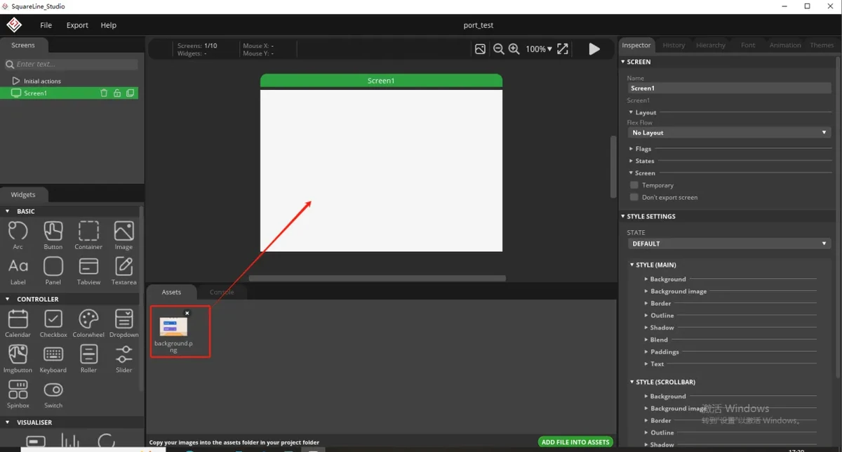
Place the background image onto the interface canvas.
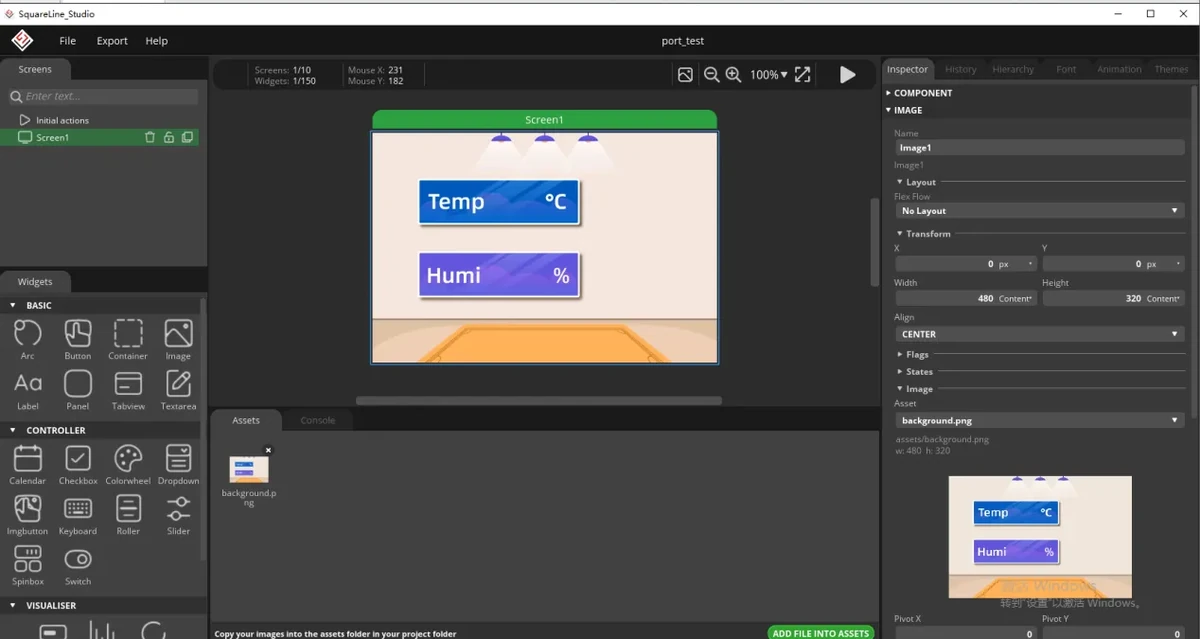
Select the image control in the left-side control or resource area, and add the background image to the current Screen. After adding, select the just-imported background image in the right-side property panel, and adjust its position and size so that it fills the entire 480 × 320 canvas. The background object exported by the current project is ui_img_background_png, and its width and height should be 480 × 320.
Add a temperature value text label.
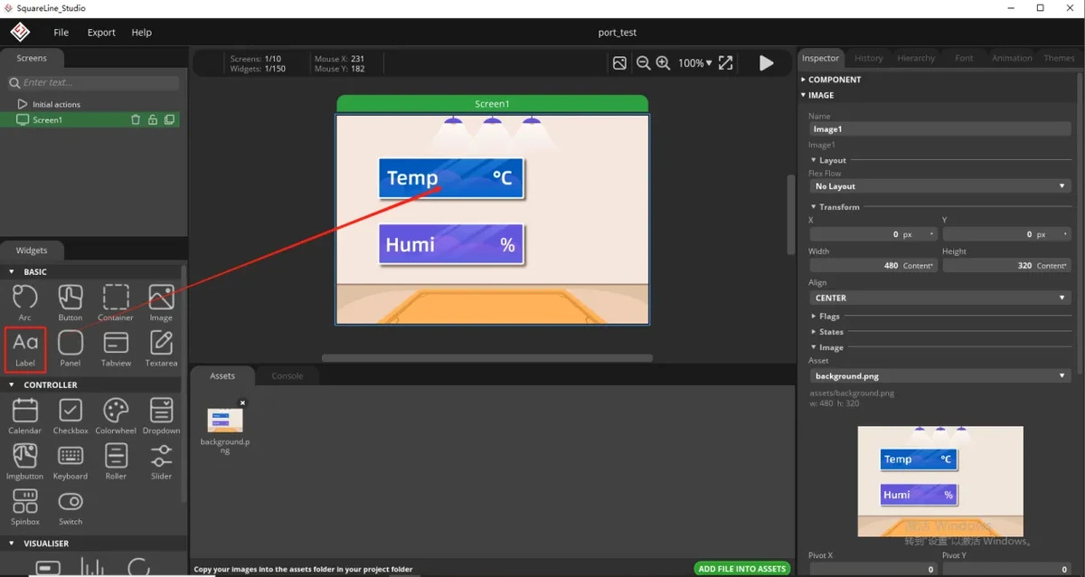
Since the screen needs to display the temperature value, a text label needs to be added to the temperature display area. After selecting the text or Label control, drag it into the temperature box so that the value displays at the position reserved by the background image. The current 3.5inch project can refer to the position in ui_Screen1.c: the temperature label is at x = -38, y = -62 relative to the screen center.
Set the object name for the temperature label.
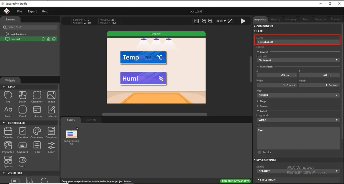
In the right-side property panel, modify the name of this label. It is recommended to keep it consistent with the object name in the code, for example TempLabel1. The subsequent ESP-IDF project code will find this label through the exported object name and write the temperature value read by the DHT20 into it.
Fill in the default display value for the temperature label.
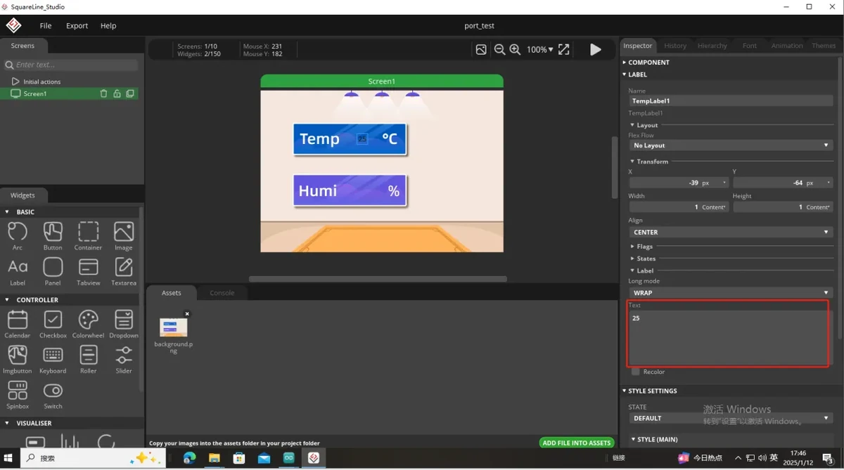
In the label text content, fill in a default temperature value, for example 25. This value is only placeholder content at the UI design stage; after the program runs, it will be replaced by the temperature value read in real time by the sensor.
Set the font style for the temperature label.
Set the label font color and size based on the background image color. To make the numbers clearly visible on the 3.5inch screen, set the font color to white and select Montserrat 20 or a font consistent with the current UI. The value will be refreshed in real time by the program later, so the label text width is recommended to remain LV_SIZE_CONTENT.
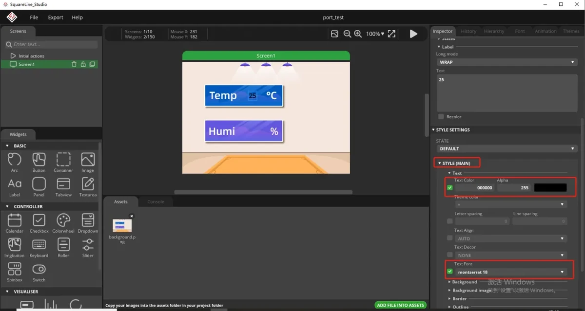
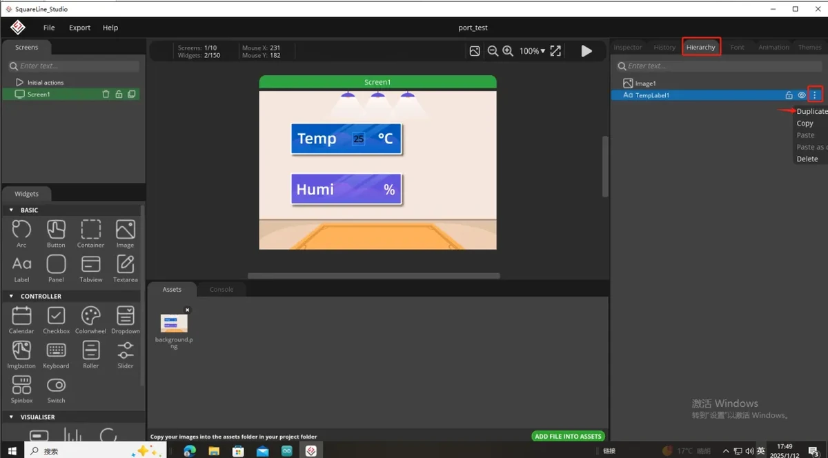
Copy the temperature label as the humidity label.
The temperature and humidity display styles are basically identical, so you can copy the temperature label you just created, then move the copied label to the humidity display area. This keeps the font size, color, and alignment of the two values consistent.
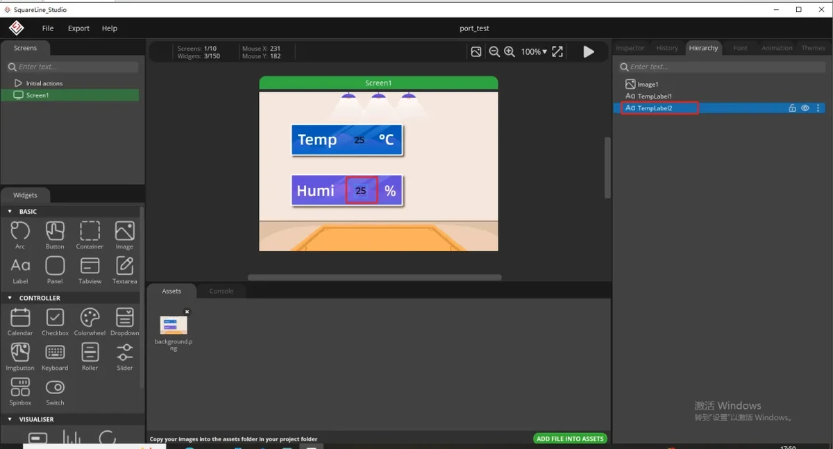
Modify the humidity label name and default value.
Select the copied label, and in the right-side property panel change the name to the humidity label object name, for example HumiLabel2; then change the default text to a humidity example value, for example 50. The code will update the humidity display through this object name.
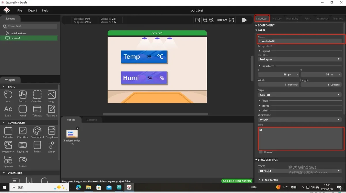
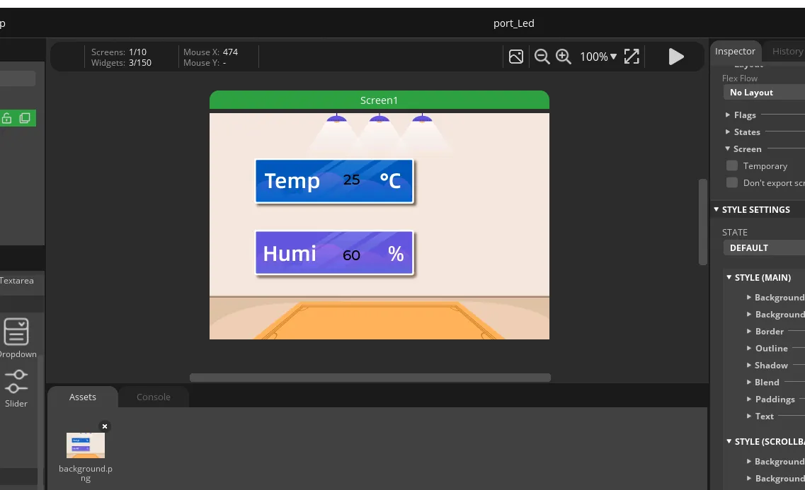
Check the overall effect of the UI interface.
After the background image, temperature label, and humidity label are all set, check whether the two values are each located in their corresponding areas, whether the font is clear, and whether there is any offset or occlusion. The 3.5inch canvas is wider than the 2.4inch one, so the labels should not remain at the center position of the 320 × 240 layout, otherwise they will be misaligned with the reserved areas of the background.
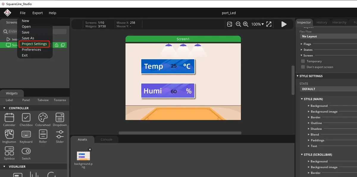
Open the project export settings.
Click Project Setting in SquareLine Studio to enter the project export configuration page. The export settings determine where the generated UI files are placed and which LVGL header file is included in the code.
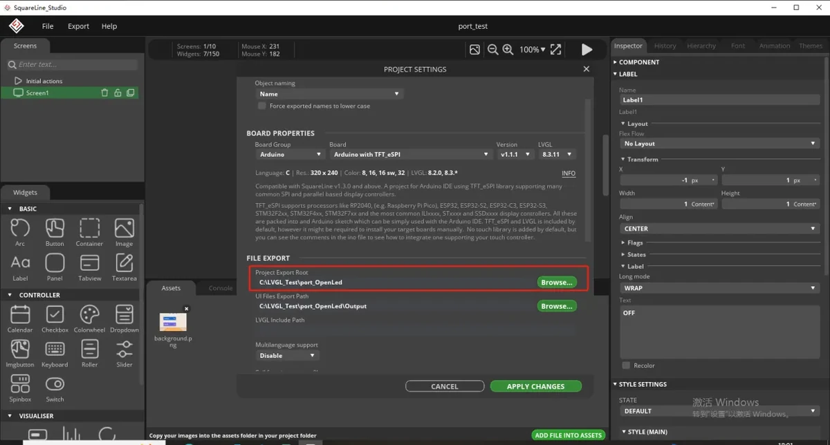
Set the UI file export path.
In the export path, select the directory used when creating the project earlier, or customize a location dedicated to saving the exported files. It is recommended that the path not contain too many nested levels, to make copying files easier later.
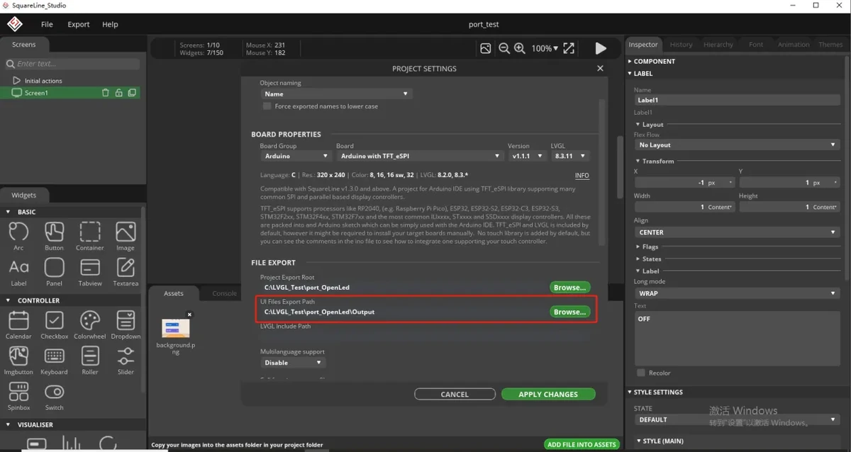
Create an Output folder to receive the exported files.
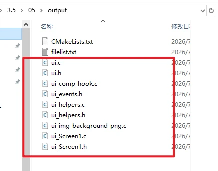
Create an Output folder under the path just set. The ui.c, ui.h, ui_helpers.*, image .c files, and so on exported by SquareLine Studio will all be placed in this folder.
Set the LVGL header file and export method.
In the project settings, fill in LVGL include as lvgl.h, and select Flat export. Flat export places the exported UI files in the same directory level, making it more convenient when copying them into the project.
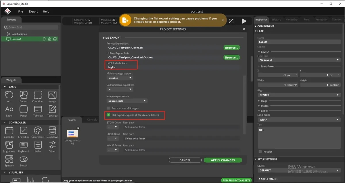
Confirm the export settings.
After checking that the export path, lvgl.h, and Flat export are all set correctly, click the confirm button to save the project settings.
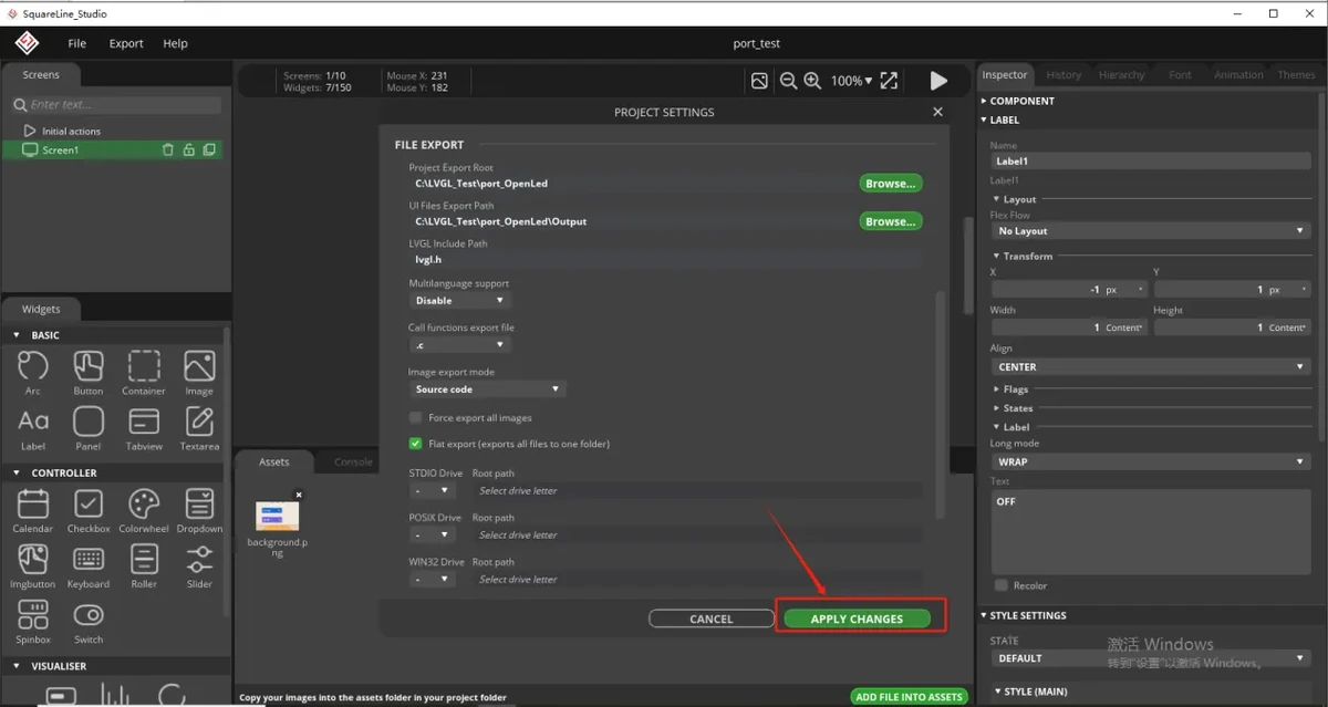
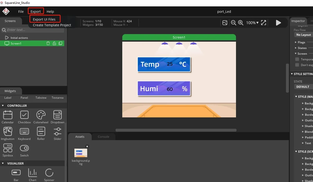
Export the UI files.
After returning to the main interface, perform the export operation to generate the UI interface files designed in this section. After the export is complete, go to the Output folder to view the generated results.
Copy the generated UI files.
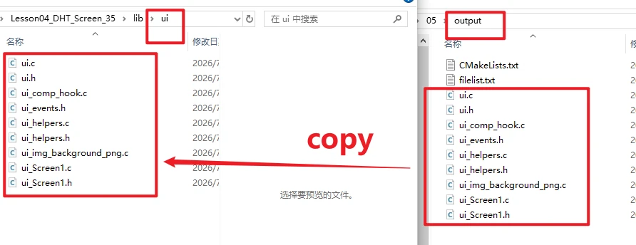
Open the Output folder you just created, and select the exported UI-related files. Typically you need to copy ui.c, ui.h, ui_helpers.c, ui_helpers.h, the interface files, the image resource .c files, and so on.
Paste into this section's project directory.
Paste the copied UI files into this section's code project directory, overwriting or replacing the original UI files.
8. Experimental Observations
Observe the screen display; the temperature and humidity values should refresh continuously.
9. Code Download
Code Download Link: Lesson04-DHT_Screen_35
Image Asset Download Link: 480x320/background.png