4.3_5.0_7.0inch_Lesson01_LVGL_Light_Control
1. Course Introduction
This lesson uses VS Code + PlatformIO to open and run the LVGL light-control UI project for the CrowPanel Advance 4.3-inch / 5.0-inch / 7.0-inch large-size development boards. The content in this large-size board series is written uniformly based on the 7.0-inch board. The software operation flow is the same for the 4.3-inch, 5.0-inch, and 7.0-inch boards, and the screen resolution is uniformly set to 800 x 480.
This project initializes the ESP32-S3, the 800x480 RGB display, GT911 touch, LVGL 9.1.0, and the UI exported from SquareLine Studio. The screen shows a desk-lamp image, along with On and Off buttons. After a button is tapped, GPIO19 controls the connected bulb or LED module to turn on or off.
The software focus of this lesson is the PlatformIO project workflow: opening the project, checking platformio.ini, confirming the source file structure, selecting the serial port, compiling, uploading, and opening the serial monitor. The UI creation process uses SquareLine Studio with the large-size 800 x 480 resolution, and the exported UI files are placed into src/ according to the PlatformIO project structure.
Reference materials:
2. Learning Objectives
- Be able to install the PlatformIO IDE extension in VS Code and open the large-size PlatformIO course project.
- Be able to explain the roles of
platformio.ini,src/,include/,images/, andboards/in this project. - Be able to complete the PlatformIO compile, upload, serial-port selection, and serial-monitor opening workflow.
- Be able to understand the relationships among the 800x480 RGB display, GT911 touch, STC8H1K28 backlight control, the LVGL flush callback, and the GPIO19 light-control event.
- Be able to use SquareLine Studio to create an
On/Offlight-control interface and integrate the exported UI files into the PlatformIO project.
3. What You Need to Prepare
3.1 Hardware
- One CrowPanel Advance 4.3-inch / 5.0-inch / 7.0-inch large-size development board. This tutorial is written based on the 7.0-inch board.
- One bulb or LED module for the light experiment. This course's code uses GPIO19 to control on/off.
- One USB data cable that supports data transfer.
Note: The large-size board has a function DIP switch. The commonly used function positions are 00 = MIC&SPK, 01 = WM (wireless module), and 11 = MIC&TF Card. Before flashing and running this lesson's LVGL light-control project, first make sure the DIP switch position does not conflict with the peripherals used in the current experiment. For later wireless-module lessons, switch to 01; for audio/TF-card related lessons, switch to the corresponding position as required by the lesson.
3.2 Software and Versions
- Visual Studio Code.
- PlatformIO IDE extension.
- PlatformIO project:
4.3_5.0_7.0_platformIO. - LVGL
9.1.0. - LovyanGFX
1.2.26. - SquareLine Studio, used to recreate or export UI files.
Code and Resource Download
Code download:
Resource download: - PlatformIO images
4. PlatformIO Software Operation Steps
Open VS Code, search for and install PlatformIO IDE in Extensions.

After installation, restart VS Code. A PlatformIO icon will appear on the left side. Click the icon to enter PIO Home.

In the Quick Access area of PIO Home, click Open Project.

In the folder selection dialog that pops up, select this lesson's project root directory:
The platformio.ini file must be visible in that directory. After selection, click to open the project.

Wait for the VS Code Explorer on the left to load the project files. Make sure the following files and directories exist:
platformio.ini
partitions.csv
boards/ESP32-S3-WROOM-1-N16R8.json
src/main.cpp
src/ui.c
src/ui_events.c
src/ui_Screen1.c
src/ui_img_table_lamp_png.c
include/LovyanGFX_Driver.h
include/pins_config.h
include/lv_conf.h
images/table_lamp.png
images/lamp-svg.png

Connect the external bulb or LED module to the GPIO19 control interface required by the lesson, and use a USB data cable to connect the CrowPanel Advance large-size development board to a USB port on your computer.

Note: The 00, 01, and 11 DIP switch positions on the large-size board switch between different function channels. The light-control lesson mainly verifies the display, touch, and GPIO19 output. If you later connect a wireless module, microphone, speaker, or TF card, first switch the DIP switch according to the corresponding lesson to avoid the function pins being routed to another channel, which would cause the experiment to be unresponsive.
Check the bottom status bar of VS Code and select the serial port corresponding to the development board. If Auto can correctly identify it, you can also keep the automatic selection.

Click the Upload icon in the bottom status bar. PlatformIO will automatically compile and upload the firmware. The first build downloads dependency libraries, so it will take longer.


Note: This tutorial uses PlatformIO's platformio.ini to manage the board, framework, partition table, and library dependencies. Do not manually modify the library source code downloaded into .pio/libdeps. If the dependencies behave abnormally, prefer cleaning the PlatformIO dependencies and then recompiling.
5. Hardware Operation Steps
Connect the external bulb or LED module, and use a USB cable that supports data transfer to connect the board to the computer.
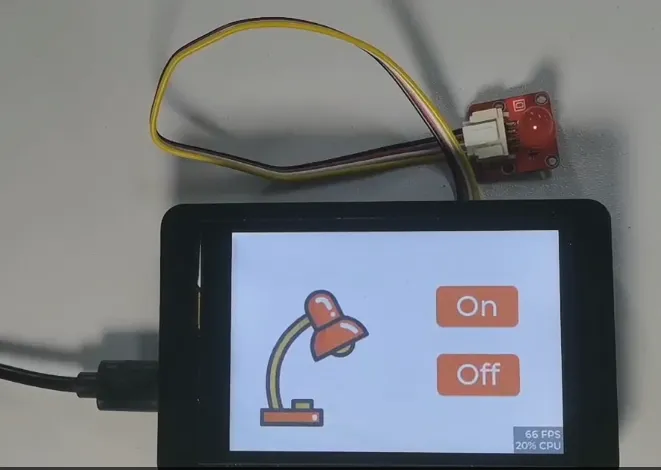
After flashing completes, wait for the board to reset. The screen should display the 800x480 light-control UI.

Tap the On and Off buttons on the screen, and observe whether the bulb or LED on the GPIO19 interface toggles on and off.

6. Key Code Explanation
6.1 PlatformIO Configuration
[env:advance-hmi]
platform = https://github.com/pioarduino/platform-espressif32/releases/download/55.03.39/platform-espressif32.zip
board = ESP32-S3-WROOM-1-N16R8
framework = arduino
monitor_speed = 115200
board_build.arduino.partitions = partitions.csv
board_upload.partitions = partitions.csv
build_flags =
    -DCONFIG_SPIRAM_SPEED_120M=1
    -DLV_CONF_INCLUDE_SIMPLE
    -I include
lib_deps =
    lvgl/lvgl@9.1.0
    adafruit/Adafruit BusIO@1.17.0
    adafruit/Adafruit SSD1306@2.5.13
    tamctec/TAMC_GT911@1.0.2
    robtillaart/TCA9554@0.1.1
    lovyan03/LovyanGFX@1.2.26
platformio.ini is the core configuration file of a PlatformIO project. This project uses the advance-hmi environment, the board definition file is boards/ESP32-S3-WROOM-1-N16R8.json, the framework is Arduino, and the serial monitor baud rate is 115200.
partitions.csv is used to configure the Flash partition table. CONFIG_SPIRAM_SPEED_120M configures the PSRAM speed for large-size display projects. LV_CONF_INCLUDE_SIMPLE and -I include let LVGL read include/lv_conf.h from the project.
6.2 Screen Resolution
include/pins_config.h defines the large-size screen resolution:
LCD_H_RES and LCD_V_RES determine the dimensions LVGL uses when creating the display device and allocating the drawing buffer. This 4.3-inch / 5.0-inch / 7.0-inch large-size course series uniformly uses 800 x 480.
Note: Large-size lessons must use an 800 x 480 resolution. If you mistakenly select 320 x 240 or 480 x 320, the UI coordinates, image sizes, and touch positions exported from SquareLine Studio will not match the screen.
6.3 RGB Display and GT911 Touch Configuration
The 800x480 RGB display and GT911 touch are configured in include/LovyanGFX_Driver.h:
cfg.memory_width = 800;
cfg.memory_height = 480;
cfg.panel_width = 800;
cfg.panel_height = 480;
cfg.freq_write = 18000000;

cfg.x_min = 0;
cfg.x_max = 800;
cfg.y_min = 0;
cfg.y_max = 480;
cfg.pin_sda = GPIO_NUM_15;
cfg.pin_scl = GPIO_NUM_16;
cfg.i2c_addr = 0x5D;
The large-size board uses an RGB parallel display, not the 2.4-inch SPI display. The touch controller is read over I2C; the GT911 address is 0x5D, with SDA on GPIO15 and SCL on GPIO16. If the screen can display but touch does not respond, first check whether the I2C device 0x5D is detected.
6.4 Backlight and Touch Control Chip
src/main.cpp scans the two I2C devices 0x30 and 0x5D at startup:
Wire.begin(15, 16);
while (1) {
  if (i2cScanForAddress(0x30) && i2cScanForAddress(0x5D)) {
    break;
  } else {
    sendI2CCommand(250);
    pinMode(1, OUTPUT);
    digitalWrite(1, LOW);
    delay(120);
    pinMode(1, INPUT);
    delay(100);
  }
}

sendI2CCommand(0);
0x30 is the address of the onboard STC8H1K28 control chip, through which the project controls the backlight and touch-panel activation flow. 0x5D is the GT911 touch address. sendI2CCommand(0) sets the backlight to its brightest state. If the screen is black but there are logs on the serial port, focus on checking whether 0x30 is recognized, whether the USB power supply is stable, and whether the DIP switch and board revision match the current lesson.
6.5 LVGL Drawing Buffer
constexpr uint32_t LVGL_BUFFER_LINES = 48;
constexpr size_t buffer_size = LCD_H_RES * LVGL_BUFFER_LINES * sizeof(uint16_t);

buf = static_cast<uint8_t *>(heap_caps_malloc(buffer_size, MALLOC_CAP_SPIRAM | MALLOC_CAP_8BIT));
buf1 = static_cast<uint8_t *>(heap_caps_malloc(buffer_size, MALLOC_CAP_SPIRAM | MALLOC_CAP_8BIT));
if (buf == nullptr || buf1 == nullptr) {
  Serial.println("Failed to allocate LVGL display buffers");
  abort();
}
The large-size screen resolution is 800 x 480, so a single frame of pixel data is large. For this reason, the project uses PSRAM to allocate two LVGL partial drawing buffers. Each buffer is 800 x 48 x 2 bytes, that is, 76,800 bytes. This way, LVGL does not need to refresh the entire screen at once; instead, it renders by region and pushes the result to the RGB display.
6.6 LVGL Flush Callback
void my_disp_flush(lv_display_t *disp, const lv_area_t *area, uint8_t *px_map) {
  if (gfx.getStartCount() > 0) {
    gfx.endWrite();
  }
  gfx.pushImageDMA(area->x1, area->y1,
                   area->x2 - area->x1 + 1,
                   area->y2 - area->y1 + 1,
                   reinterpret_cast<lgfx::rgb565_t *>(px_map));
  gfx.waitDMA();

  lv_display_flush_ready(disp);
}
After LVGL finishes rendering a region, it calls my_disp_flush(). area represents the rectangular region that needs to be refreshed, and px_map is the RGB565 pixel data prepared by LVGL. The function pushes the image to the screen via gfx.pushImageDMA(). After the DMA completes, lv_display_flush_ready() must be called to tell LVGL that the current buffer can be reused.
6.7 Touch Read Callback
void my_touchpad_read(lv_indev_t *indev, lv_indev_data_t *data)
{
  data->state = LV_INDEV_STATE_REL;
  bool touched = gfx.getTouch(&touch_x, &touch_y);
  if (touched)
  {
    data->state = LV_INDEV_STATE_PR;
    data->point.x = touch_x;
    data->point.y = touch_y;
  }
}
gfx.getTouch() reads the touch coordinates from the GT911. When there is no touch, the state is LV_INDEV_STATE_REL; once a touch is detected, the state changes to LV_INDEV_STATE_PR, and the coordinates are passed to LVGL. For the large-size project, the touch coordinate ranges are 0~800 and 0~480, which match the screen resolution.
6.8 Light-Control Events
void Lamp_on(lv_event_t * e)
{
    digitalWrite(19, HIGH);
}

void Lamp_off(lv_event_t * e)
{
    digitalWrite(19, LOW);
}
src/ui_events.c is obtained by organizing the file exported from SquareLine Studio. Lamp_on / Lamp_off are event functions bound to the UI buttons. Tapping the On button drives GPIO19 high; tapping the Off button drives GPIO19 low.
6.9 setup() Initialization Flow
void setup()
{
  Serial.begin(115200);
  pinMode(19, OUTPUT);

  Wire.begin(15, 16);
  sendI2CCommand(0);

  gfx.init();
  gfx.initDMA();
  gfx.startWrite();
  gfx.fillScreen(TFT_BLACK);

  lv_init();
  lv_tick_set_cb(my_tick_get_cb);

  lv_display_t *display = lv_display_create(LCD_H_RES, LCD_V_RES);
  lv_display_set_color_format(display, LV_COLOR_FORMAT_RGB565);
  lv_display_set_flush_cb(display, my_disp_flush);
  lv_display_set_buffers(display, buf, buf1, buffer_size, LV_DISPLAY_RENDER_MODE_PARTIAL);

  lv_indev_t *indev = lv_indev_create();
  lv_indev_set_type(indev, LV_INDEV_TYPE_POINTER);
  lv_indev_set_read_cb(indev, my_touchpad_read);

  ui_init();
  Serial.println("Setup done");
}
The initialization order is the main thread for troubleshooting: first open the serial port and GPIO19, then start I2C and turn on the backlight; next initialize LovyanGFX, DMA, LVGL, the drawing buffer, the display device, and the touch input device; finally call ui_init() to create the interface exported from SquareLine Studio.
6.10 Main Loop Keeps LVGL Running
lv_timer_handler() must run continuously so that LVGL can refresh the interface, read touch input, and trigger button events. Here a 1 ms delay per loop keeps the interface responsive.
7. UI Creation Steps
This section's UI is created using SquareLine Studio. For large-size projects, the canvas must be set to 800 x 480. The exported UI files are finally copied into the PlatformIO project, where src/main.cpp is responsible for the display driver, touch driver, and LVGL runtime.
For SquareLine Studio download and basic installation, refer to:
Create LVGL UI with SquareLine Studio
7.1 Creating a SquareLine Project
Open SquareLine Studio and click Create at the top. When creating a new project, select LVGL 9.1.0.
In the board category, select the TFT_eSPI-compatible template category shown by SquareLine Studio.
Select the TFT_eSPI project template.

Confirm the resolution based on the large-size display. The course projects for 4.3-inch / 5.0-inch / 7.0-inch displays all use 800 x 480.

In the Project Settings on the right, set the project name and path, and confirm the key parameters:
After confirming the parameters, click CREATE to create the project.
7.2 Importing the Desk Lamp Image Assets
After entering the project editing interface, switch to the Assets area at the bottom.
Click ADD FILE INTO ASSETS to import the desk lamp image assets into the project resources.

The local assets for this project are located at:
The image assets can also be obtained from the PlatformIO project directory in the code repository.

After importing, drag the desk lamp image asset onto the Screen1 canvas. Adjust its position on the 800x480 canvas so that it sits on the left side of the screen, leaving the right side for the button area.

7.3 Adding the On Button
In the left panel under Widgets > BASIC, select Button.
Drag the Button onto the right side of the canvas to serve as the On button.

Select the button and adjust its position and size in the Inspector on the right.

Expand STYLE (MAIN) > Background and set the button background color to orange-red; for example, you can use F1412F.
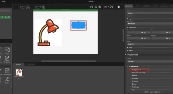
Add a Label from the left Widgets > BASIC and drag it into the button.

Select the Label and change its text to On in the text box on the right.

Adjust the Label style, set the text color to white, and choose an appropriate font size. The example project uses montserrat 40.

In the Hierarchy panel on the right, confirm that Label is a child of Button.

7.4 Duplicating and Creating the Off Button
In the Hierarchy panel, select the finished Button1.
Open the more menu and select Copy.
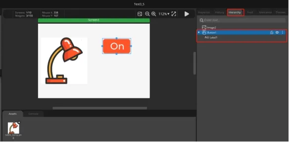
Paste it on the canvas or in the hierarchy as a new button.

Move the duplicated button below the On button.

Select the Label in the new button and change its text to Off.

Adjust the position and background color of both buttons as needed so that the On / Off buttons are arranged vertically on the right side.

7.5 Configuring Button Events
Select the On button and scroll the Inspector on the right down to the EVENTS area.
Click ADD EVENT to add an event.
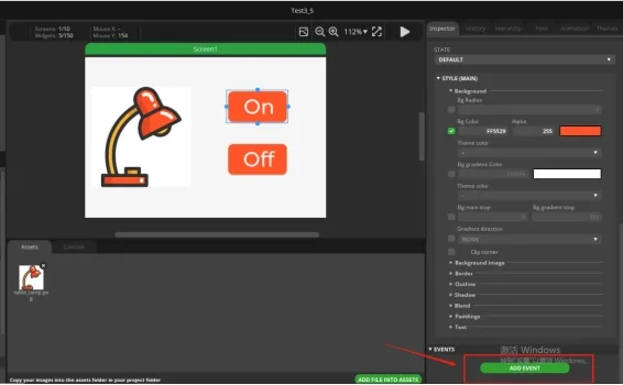
Set Trigger to RELEASED.
Select CALL FUNCTION for Action.
Enter the function name:

Select the Off button and add an event the same way.
Set Trigger to RELEASED, select CALL FUNCTION for Action, and enter the function name:

Note: The function name used in Call function must match exactly the function name in the PlatformIO project. In this lesson, the On button uses Lamp_on and the Off button uses Lamp_off; any mismatch in capitalization will prevent the button from controlling GPIO19.
Click the play button in the top-right corner to enter preview mode and check whether the On / Off buttons can be tapped normally.


7.6 Setting the Export Path
Click File > Project Settings to open the project settings.

In FILE EXPORT, set the export path. In the example, Project Export Root points to the SquareLine project directory and UI Files Export Path points to the Output folder.

Set LVGL Include Path to:
Check Flat export (exports all files to one folder), then click APPLY CHANGES.

Note: It is recommended to check Flat export so that the exported UI files are consolidated into a single folder, making it less likely to miss files when copying them into the PlatformIO project later.
7.7 Copying UI Files to the PlatformIO Project
After the UI files are exported.

Copy the UI source files generated by SquareLine Studio into the PlatformIO project:
The current project already places the UI files exported from SquareLine Studio in src/:
src/ui.c
src/ui.h
src/ui_events.c
src/ui_events.h
src/ui_Screen1.c
src/ui_Screen1.h
src/ui_img_table_lamp_png.c
src/ui_helpers.c
src/ui_helpers.h
src/ui_comp_hook.c

After copying, run PlatformIO Upload again. If you only modified the UI files, you can also run Build first to confirm there are no missing header files, function names, or image resources, then upload to the development board to verify.
8. Experimental Results
After flashing is complete, the large-size display shows the 800x480 lamp control interface. Tapping the On button on the screen sets GPIO19 to a high level, and the external bulb or LED lights up; tapping the Off button sets GPIO19 to a low level, and the bulb or LED turns off.
Note: If the experiment involves a WM wireless module, MIC&SPK, or MIC&TF Card, first check the DIP switch. The positions 00, 01, and 11 correspond to different functions; an incorrect setting will prevent the peripheral channel from working as expected.
9. Code Download
PlatformIO project link: PlatfromIO
Image assets link: PlatformIO images