PlatformIO_LVGL_5.0: 5.0-Inch Temperature and Humidity Display with Touch-Controlled LED under PlatformIO
1. Course Introduction
In this lesson, we use VS Code, PlatformIO, the Arduino framework, LVGL 9.1.0, LovyanGFX (the version bundled in the project), and SquareLine Studio 1.6.1 to drive the CrowPanel ESP32-S3 5.0-inch display. The program reads temperature and humidity from the DHT20 over the I2C bus on GPIO19/GPIO20, displays the values on the 800 × 480 screen through LVGL, and controls the LED on GPIO38 via an ON/OFF touch button.
Learners must first prepare the development environment and hardware, open the course project, complete the build, select the serial port, and flash the firmware, then observe the screen, LED, and serial monitor. During normal operation, the LCD backlight turns on, the temperature and humidity labels show values, the LED state changes after the button is pressed, and the serial port outputs coordinates on touch. This lesson uses the same set of UI resources as the Arduino version; the difference is that the project is managed by PlatformIO for dependencies and the build process.
Reference materials:
2. Learning Objectives
- Be able to install PlatformIO in VS Code and open the course project.
- Be able to explain the role of
platformio.ini,src/,include/, andlib/in this project. - Be able to complete the connections for the DHT20, LED, USB, and display, and follow the PlatformIO workflow to build, flash, and open the serial monitor.
- Be able to use SquareLine Studio 1.6.1 to create an 800 × 480 UI with LVGL 9.1.0 and integrate the exported files into the PlatformIO project.
- Be able to determine whether the experiment succeeded based on the on-screen display, button response, LED state, and serial coordinates.
3. Preparations
3.1 Hardware
- One CrowPanel ESP32-S3 5.0-inch development board.
- One DHT20 temperature and humidity module, connected to GPIO19 (SDA) and GPIO20 (SCL).
- One LED module, connected to GPIO38.
- A 4-pin connector cable and a USB data cable that supports data transfer.
3.2 Software and Versions
- Visual Studio Code.
- PlatformIO IDE extension.
- LVGL
9.1.0. - SquareLine Studio
1.6.1.
4. Software Operation Steps
Open VS Code, search for and install PlatformIO IDE in Extensions.
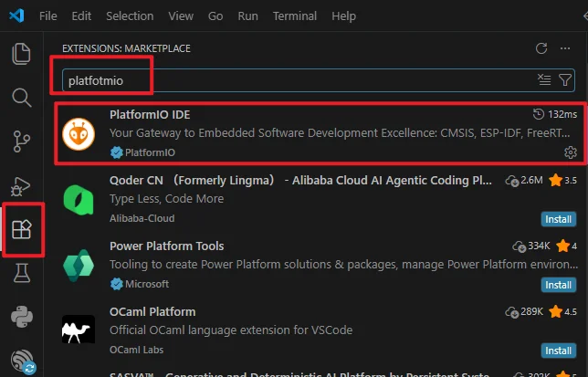
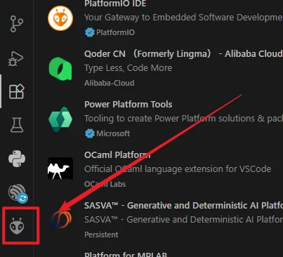
After installation completes, restart VS Code; the PlatformIO icon should appear on the left side. Click the icon to enter the PIO Home main page.
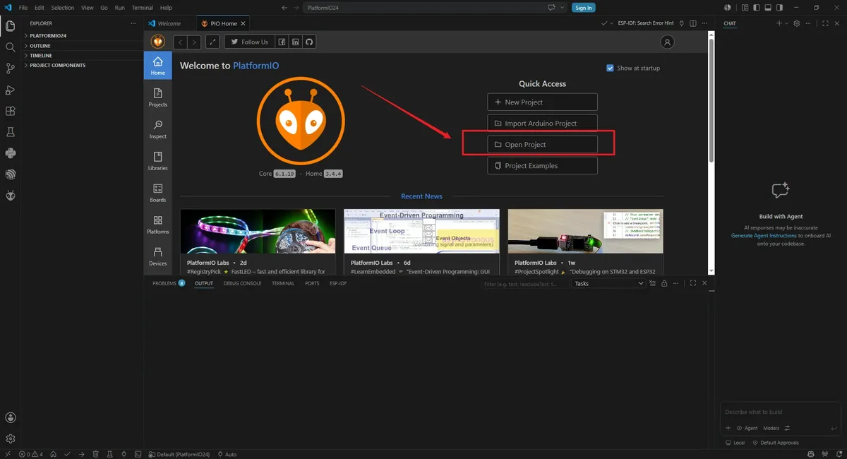
In the PIO Home Quick Access area, click Open Project.
In the dialog, browse to the path and select the project root folder PlatformIO50 (the folder must contain platformio.ini), then click the blue Open "PlatformIO50" button.
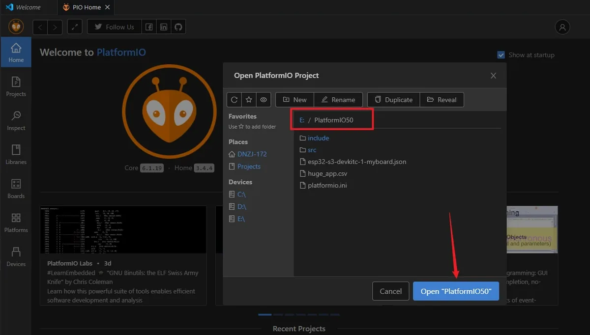
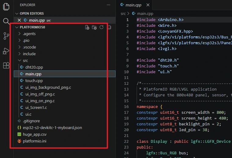
The project loads in the left-side Explorer
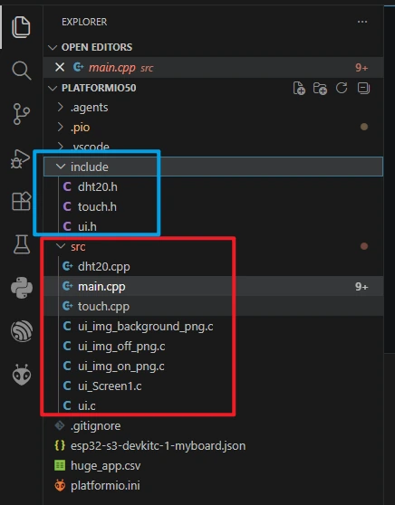
src/main.cpp: main program code.
platformio.ini: platform configuration file.
include is the header file directory; project dependencies are provided by platformio.ini and the Arduino/libraries in the course code.
Open main.cpp to review the project code.
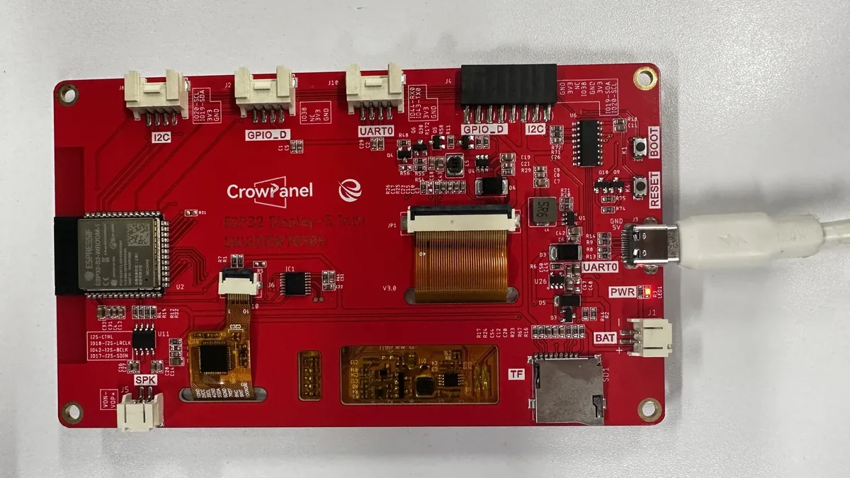
Connect the CrowPanel development board to a USB port on your computer using a USB data cable.
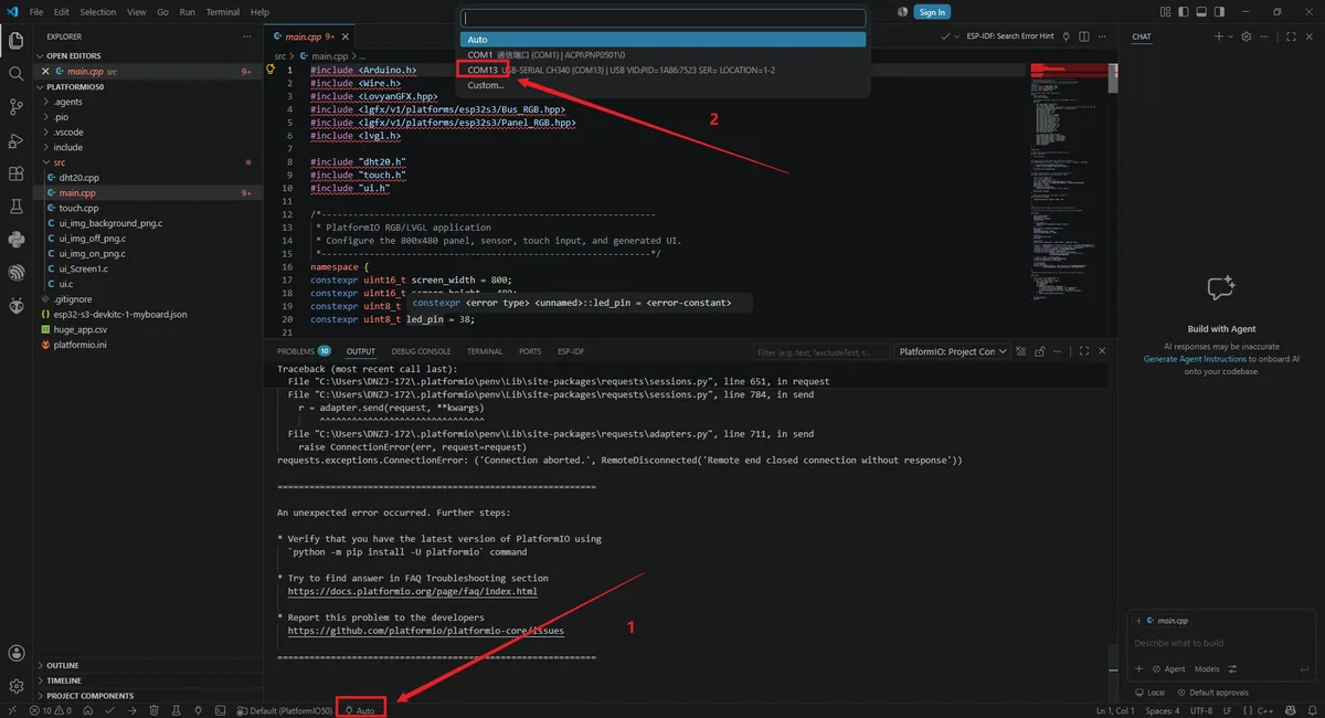
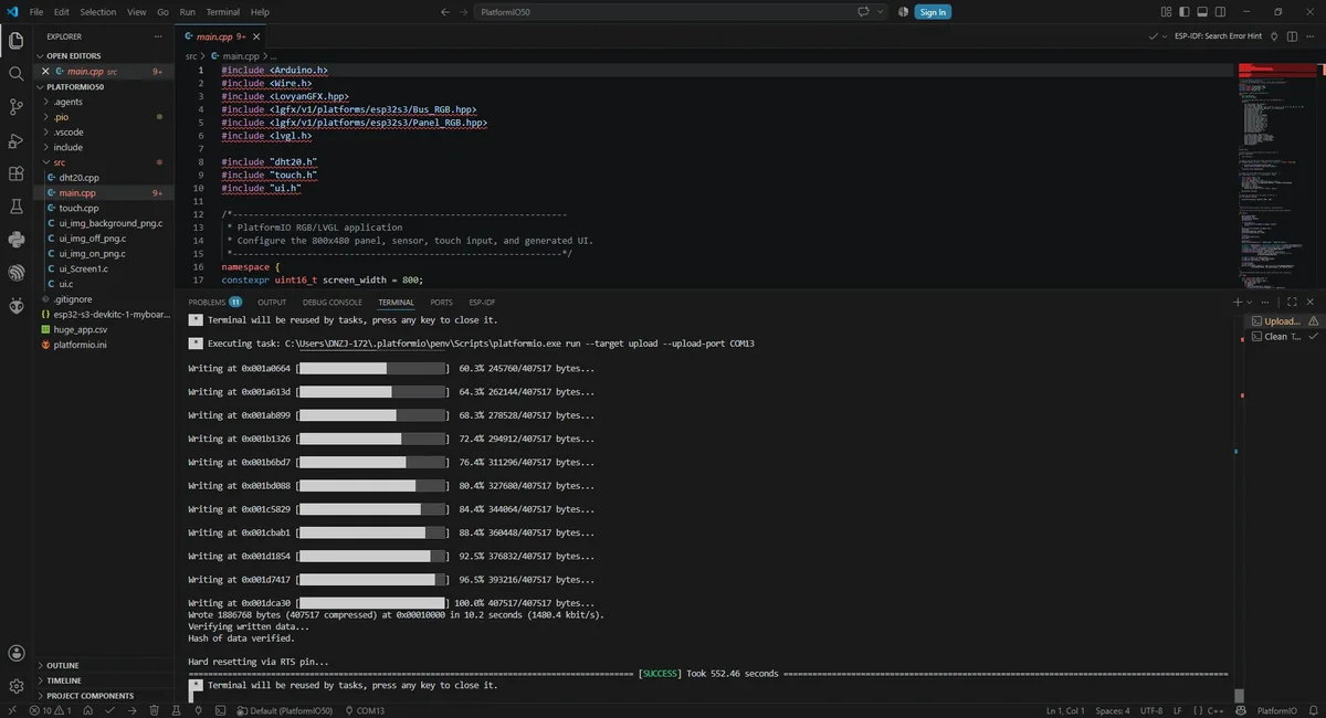
Select the device serial port: check the bottom status bar of VS Code; the left dropdown defaults to Auto. Click the dropdown and select the serial port corresponding to the development board (example: COM13).
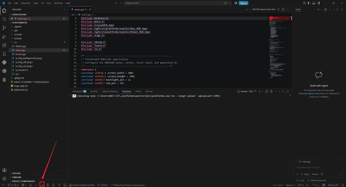
Click the right-arrow icon (PlatformIO: Upload) in the bottom status bar of VS Code. Wait for the build and upload process to run automatically.

5. Hardware Operation Steps
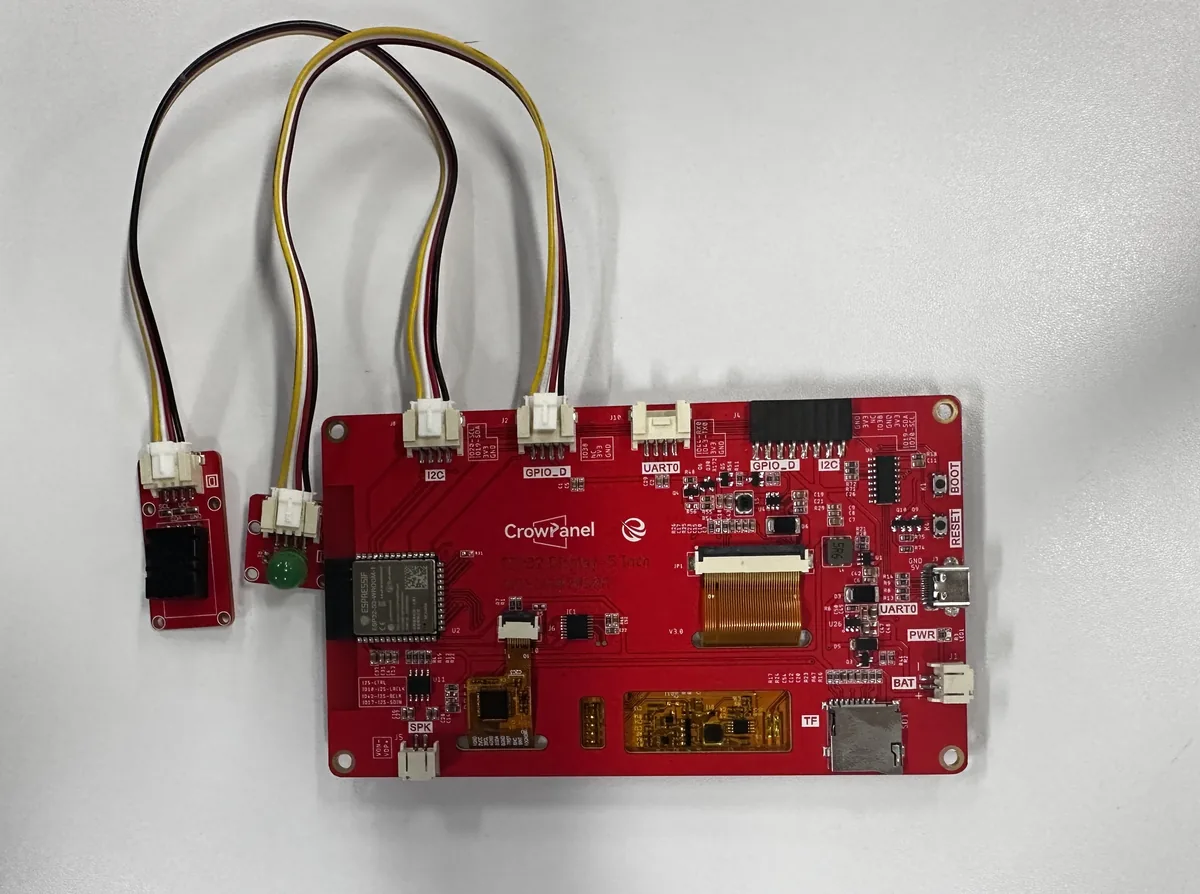
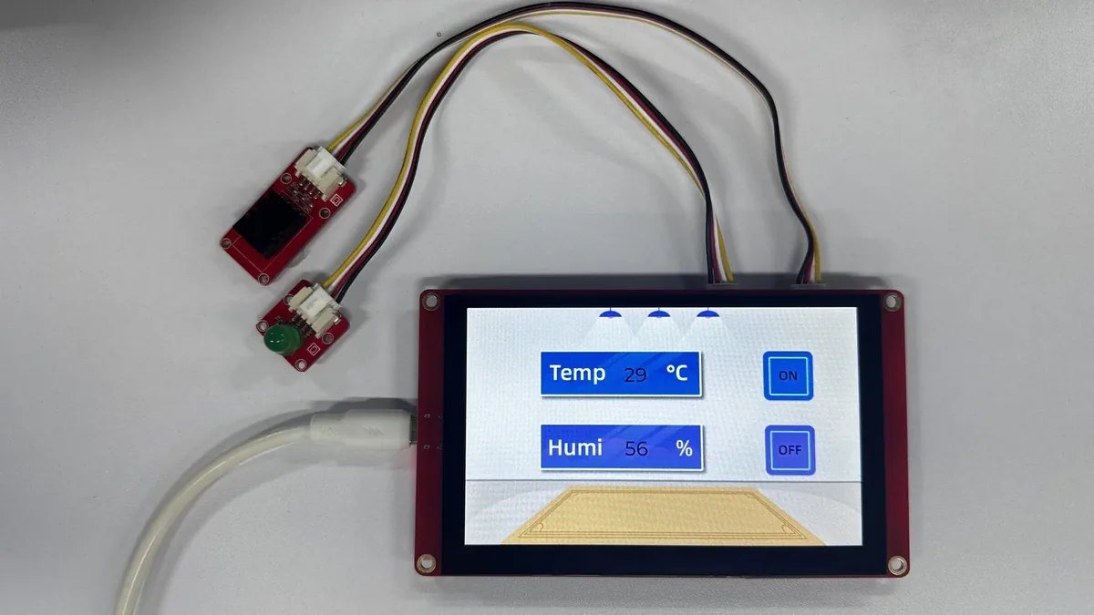
Wire the connections according to the diagram:
-
DHT20 temperature and humidity sensor → main board I2C interface.
-
LED module → main board GPIO_D interface.
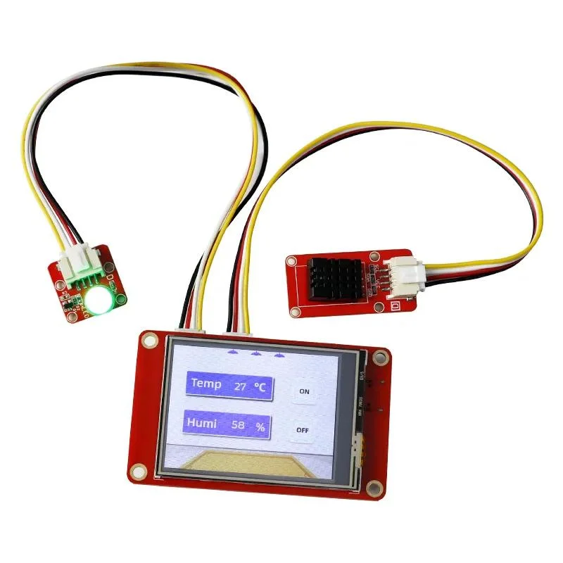
Displays real-time temperature and humidity (data collected by the DHT20) and provides ON/OFF buttons to turn the external LED on/off.
ON → LED on.
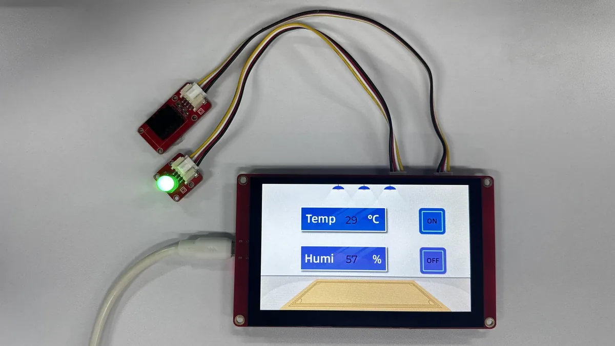
OFF → LED off.
6. Key Code Explanation
6.1 Pinning the Platform, Board, Partition, and LVGL Version
[env:esp32s3]
; Pin the framework and custom board definition used by this hardware.
platform = https://github.com/pioarduino/platform-espressif32/releases/download/55.03.38/platform-espressif32.zip
board = esp32-s3-devkitc-1-myboard
framework = arduino
board_build.partitions = huge_app.csv
; Change only these ports when the board enumerates under another COM number.
upload_port = COM16
monitor_port = COM16
monitor_speed = 115200
; Keep the UI API compatible with LVGL 9.1.0 and use the bundled display driver.
lib_deps =
    lvgl/lvgl@9.1.0
    file://../Arduino/libraries/LovyanGFX
platformio.ini pins the pioArduino platform, LVGL 9.1.0, the in-project LovyanGFX, and a custom ESP32-S3 board. When the computer's port is not COM16, only modify upload_port and monitor_port; do not change the display parameters.
6.2 Configuring RGB Panel Size and Timing
// These values bind LVGL and the application outputs to the 5.0-inch board.
constexpr uint16_t screen_width = 800;
constexpr uint16_t screen_height = 480;
constexpr uint8_t backlight_pin = 2;
constexpr uint8_t led_pin = 38;

class Display : public lgfx::LGFX_Device {
public:
    lgfx::Bus_RGB bus;
    lgfx::Panel_RGB panel;

    /** Configure RGB timing, data pins, and the 800x480 panel. */
    Display()
    {
        // Keep the frame-buffer geometry equal to the physical panel size.
        auto panel_config = panel.config();
        panel_config.memory_width = screen_width;
        panel_config.memory_height = screen_height;
        panel_config.panel_width = screen_width;
        panel_config.panel_height = screen_height;
        panel.config(panel_config);
        panel.setBus(&bus);
        setPanel(&panel);
    }
};
The panel and memory sizes must remain 800×480. The RGB data pins and porch parameters are located in the bus configuration of the same constructor and should only be modified after the hardware timing has been verified.
6.3 Registering the Full Double Frame Buffer and Touch Input
// Attach LovyanGFX's two full frames so LVGL can swap them at VSYNC.
lv_color_t * frame_buffer_0 = reinterpret_cast<lv_color_t *>(lcd.bus.getFrameBuffer(0));
lv_color_t * frame_buffer_1 = reinterpret_cast<lv_color_t *>(lcd.bus.getFrameBuffer(1));
lv_display_t * display = lv_display_create(screen_width, screen_height);
lv_display_set_color_format(display, LV_COLOR_FORMAT_RGB565);
lv_display_set_flush_cb(display, display_flush);
lv_display_set_buffers(display, frame_buffer_0, frame_buffer_1,
                       screen_width * screen_height * sizeof(lv_color_t),
                       LV_DISPLAY_RENDER_MODE_FULL);

// Register GT911 as LVGL's pointer source for generated UI widgets.
lv_indev_t * touch = lv_indev_create();
lv_indev_set_type(touch, LV_INDEV_TYPE_POINTER);
lv_indev_set_read_cb(touch, touch_read);
The full double frame buffer is provided by the LovyanGFX RGB bus, and LVGL uses RGB565 and the FULL mode. If the PSRAM or custom board memory configuration is incorrect, the lcd.begin() or frame buffer acquisition stage will fail.
6.4 Frame Flushing and GT911 Touch Reading
/** Present the full RGB frame buffer selected by LovyanGFX. */
void display_flush(lv_display_t * display, const lv_area_t *, uint8_t * pixel_map)
{
    // Present the full buffer at VSYNC, then let LVGL render the next frame.
    if (!lcd.bus.presentFrameBuffer(pixel_map)) {
        Serial.println("Display frame switch timeout");
    }
    lv_display_flush_ready(display);
}

/** Supply the latest GT911 point and log each new press. */
void touch_read(lv_indev_t *, lv_indev_data_t * data)
{
    static int16_t last_x = 0;
    static int16_t last_y = 0;
    static bool was_pressed = false;
    // Preserve the last coordinates while exposing the current press state.
    const bool pressed = touch_read_point(last_x, last_y);
    data->state = pressed ? LV_INDEV_STATE_PRESSED : LV_INDEV_STATE_RELEASED;
    data->point.x = last_x;
    data->point.y = last_y;
    // Log only the transition into a press to avoid flooding the serial port.
    if (pressed && !was_pressed) {
        Serial.printf("Touch %d,%d\n", last_x, last_y);
    }
    was_pressed = pressed;
}
The flush-complete notification must not be removed. was_pressed prints coordinates only on a new press, avoiding flooding the serial port while the finger stays still.
6.5 Discovering the GT911 Address and Reading Touch Points
/**
 * @brief Reset the touch hardware and discover its active I2C address.
 */
void touch_init()
{
    touch_reset();
    uint8_t product_id[4];
    // Probe both common GT911 addresses because the reset level selects one.
    for (uint8_t address : gt911_addresses) {
        if (gt911_read_at(address, gt911_product_id, product_id, sizeof(product_id))) {
            gt911_address = address;
            Serial.printf("GT911 found at 0x%02X, ID %.4s\n", address, product_id);
            return;
        }
    }
    Serial.println("GT911 not found");
}

/**
 * @brief Read the first active point and clamp it to the 800x480 panel.
 */
bool touch_read_point(int16_t & x, int16_t & y)
{
    // Decode little-endian coordinates and keep them inside LVGL's bounds.
    const uint16_t raw_x = point[1] | (point[2] << 8);
    const uint16_t raw_y = point[3] | (point[4] << 8);
    x = constrain(raw_x, 0, 799);
    y = constrain(raw_y, 0, 479);
    return true;
}
The driver probes the common GT911 addresses 0x5D and 0x14 and clamps touch points within the screen bounds. When GT911 not found appears on the serial port, first check I2C 19/20, the PCA9557 reset sequence, and the power supply.
6.6 DHT20 Parsing and UI Update
/**
 * @brief Trigger a conversion and decode integer temperature/humidity values.
 * @param temperature Output temperature in degrees Celsius.
 * @param humidity Output relative humidity in percent.
 * @return true when a complete measurement is available.
 */
bool dht20_read(int & temperature, int & humidity)
{
    // Start one measurement; the sensor raises its busy bit during conversion.
    const uint8_t measure_command[] = {0xAC, 0x33, 0x00};
    if (!write_command(measure_command, sizeof(measure_command))) {
        return false;
    }
    // The complete source waits for conversion, checks the busy bit,
    // and converts the two 20-bit raw values to integer units.
}
// Read the DHT20 once per second while servicing LVGL every iteration.
if (now - last_sensor_read >= 1000) {
    last_sensor_read = now;
    int temperature;
    int humidity;
    if (dht20_read(temperature, humidity)) {
        lv_label_set_text_fmt(ui_TempLabel, "%d", temperature);
        lv_label_set_text_fmt(ui_HumiLabel, "%d", humidity);
        Serial.printf("DHT20: %d C, %d %%\n", temperature, humidity);
    } else {
        Serial.println("DHT20 read failed");
    }
}
On a sensor read failure, keep the previous label and print an error. ui_TempLabel and ui_HumiLabel must match the exported UI object names.
6.7 Isolating UI and GPIO through Callbacks
/** Apply the generated UI's LED request to GPIO 38. */
void set_led(bool enabled)
{
    digitalWrite(led_pin, enabled ? HIGH : LOW);
}

void ui_init(ui_led_callback_t led_callback)
{
    // Retain the application callback before generated widgets can emit events.
    set_led = led_callback;
    ui_Screen1_screen_init();
    lv_screen_load(ui_Screen1);
}
The PlatformIO version passes the hardware control function to the UI as a callback. This way, the generated UI files do not need to know about GPIO38 directly, and the application-layer hardware logic is easier to preserve when re-exporting the interface.
7. UI Resource Creation and Integration
This section uses SquareLine Studio 1.6.1 to demonstrate the interface creation method again. The course already provides the exported UI files, so beginners can first read this section to understand the workflow and then use the files in the project directly to complete the build. When creating a new project, you must select LVGL 9.1.0;
How to download SquareLine Studio:https://www.elecrow.
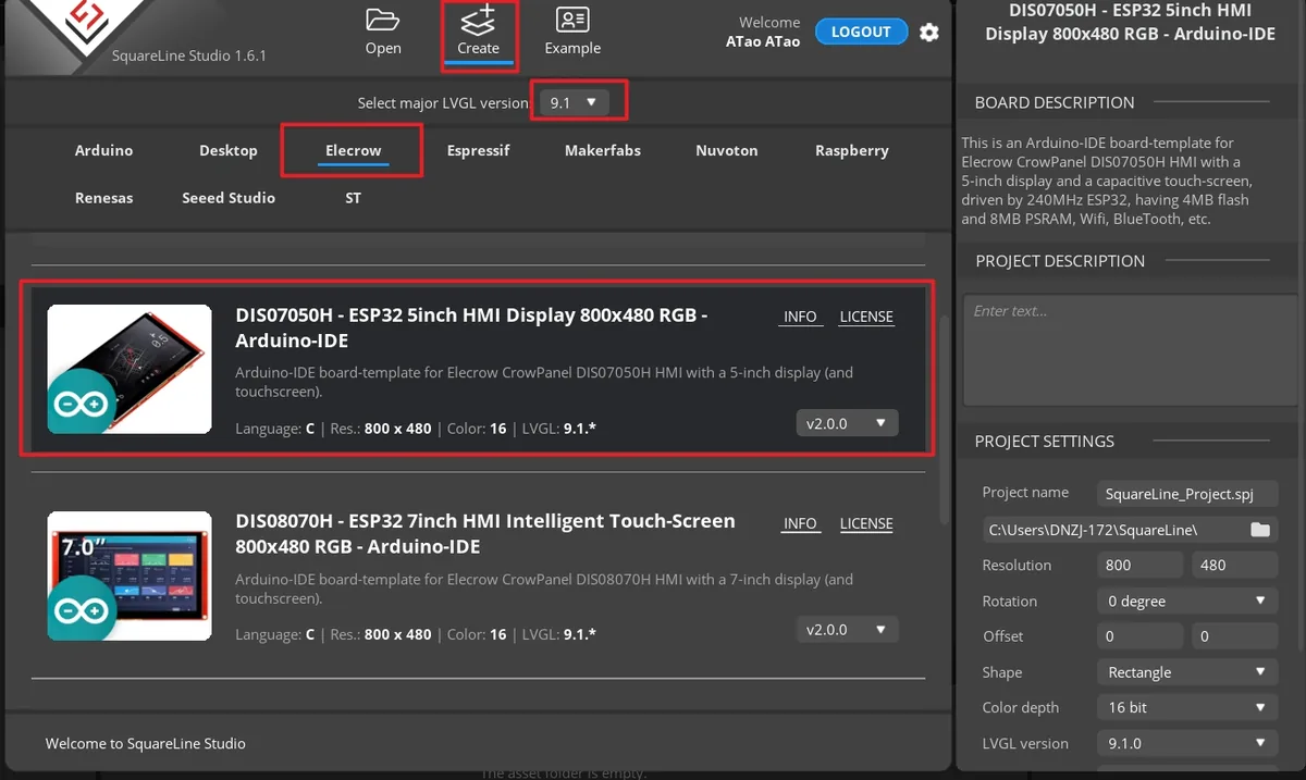
Open SquareLine Studio 1.6.1, click Create at the top to create a new project, select 9.1 as the LVGL major version, and choose Elecrow under the vendor category. In the template list, select DIS07050H - ESP32 5inch HMI Display 800x480 RGB - Arduino-IDE. This template is designed for the Elecrow CrowPanel 5-inch capacitive touchscreen, with preset parameters of 800×480 resolution and LVGL 9.1. Complete the project creation.
Note: This template is a dedicated Arduino project template for the Elecrow CrowPanel. It directly generates LVGL UI code that matches the hardware. If you switch to a different display model, you must select the corresponding hardware template and verify the resolution and color-depth settings.
Enter a project name, set the LVGL version to 9.1.0, set the resolution to width 800 and height 480, set the color depth to 16 bit, and then click CREATE. After creation, the canvas should be in landscape orientation at 800×480.
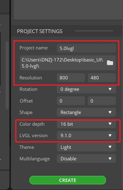
Note: A 16 bit color depth can represent 65,536 colors using RGB 5:6:5 pixel encoding. Keep it consistent with the project's color configuration.
After the project opens, select Screen1 under Screens on the left, confirm that the central canvas is blank and that the Inspector on the right shows the Screen properties. All subsequent widgets will be added to this page.
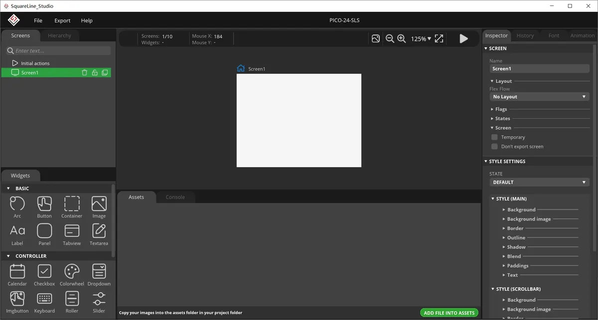
In the Assets area, click ADD FILE TO ASSETS and import background.png, on.png, and off.png in turn. After importing, you should see three thumbnails.
Material link:
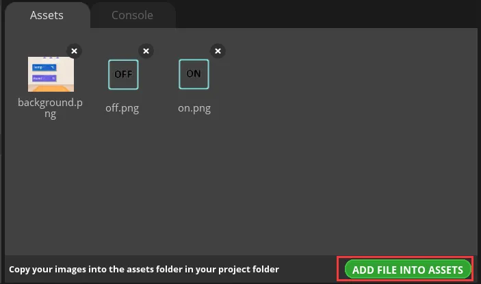
Notes: Image assets support PNG format only; the pixel dimensions of an image should be smaller than the project's screen size; a single image should not exceed 100 KB, and preferably should be kept within 30 KB, to avoid affecting display smoothness.
Select Screen1, expand STYLE SETTINGS > STYLE (MAIN) > Background on the right, and enable the background image setting.
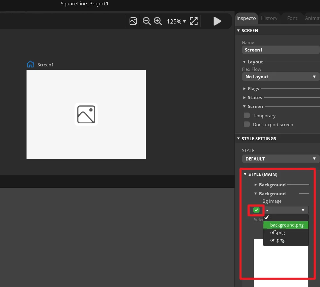
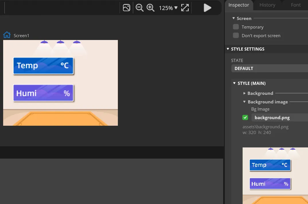
Select background under Bg Image. The canvas should immediately display the course background image, and the background should fully cover the entire page.
Click Label in the Widgets panel on the left to add Label1 to Screen1. This label will be updated by the program with the temperature value.
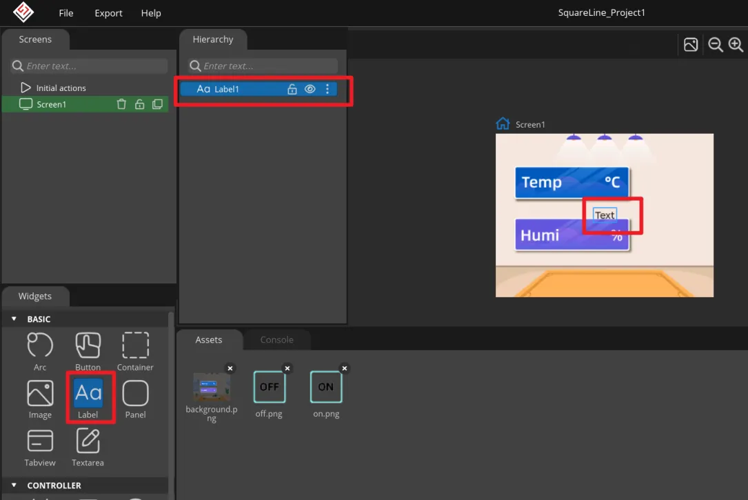
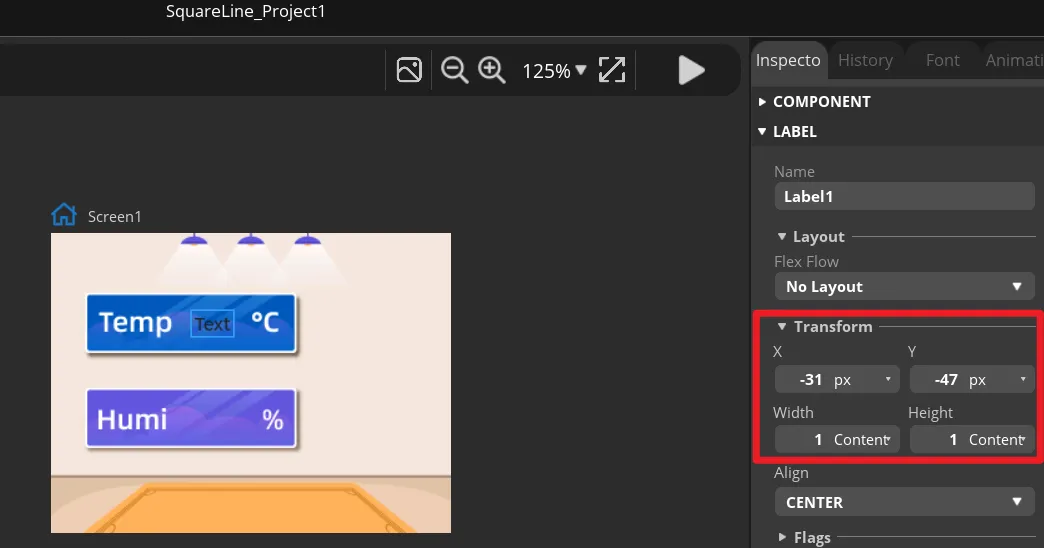
Select Label1 and adjust its X and Y position and its width and height under Transform so that it sits within the temperature display area of the background image. You can also drag it first and then fine-tune with the numeric values.
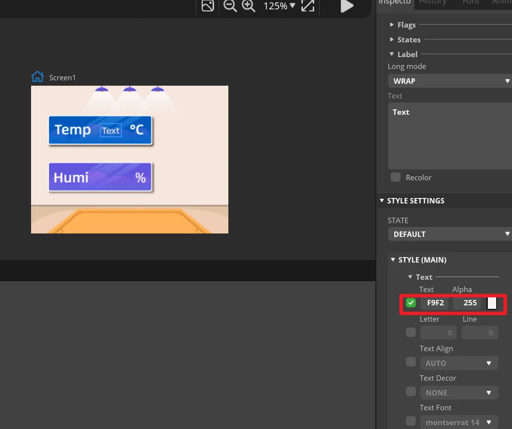
Under STYLE (MAIN) of Label1, change the text color to white and set an appropriate font size. The text on the canvas should be clearly visible and should not overflow the background frame.
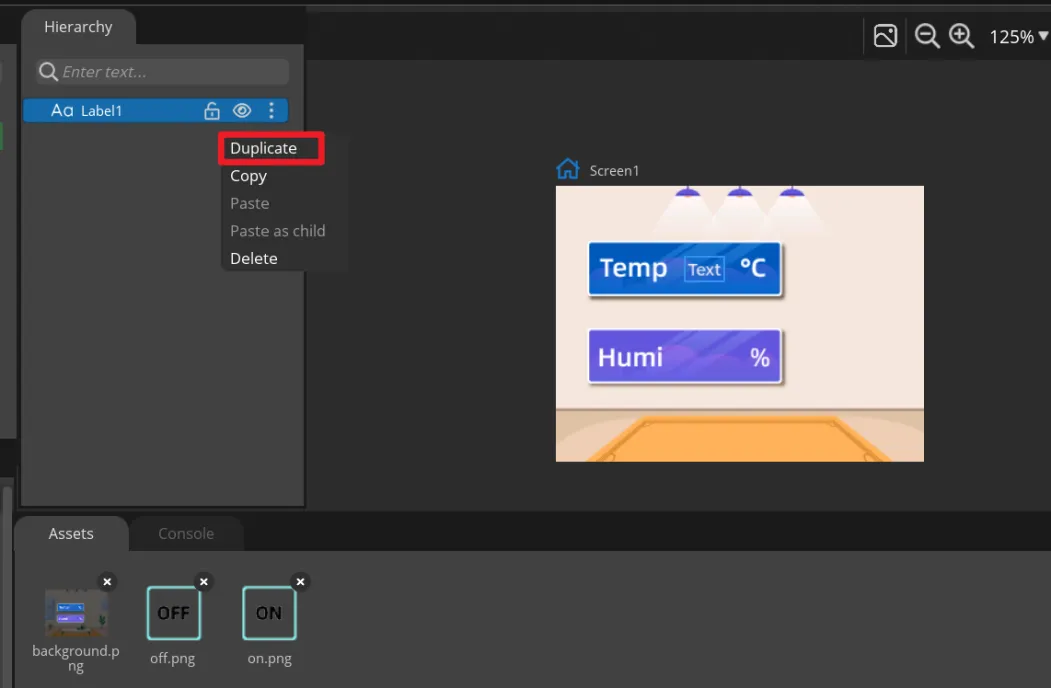
Right-click Label1 and select Duplicate to create Label2, then move it to the humidity display area. Keep the names Label1 and Label2, because the main program updates them by name.
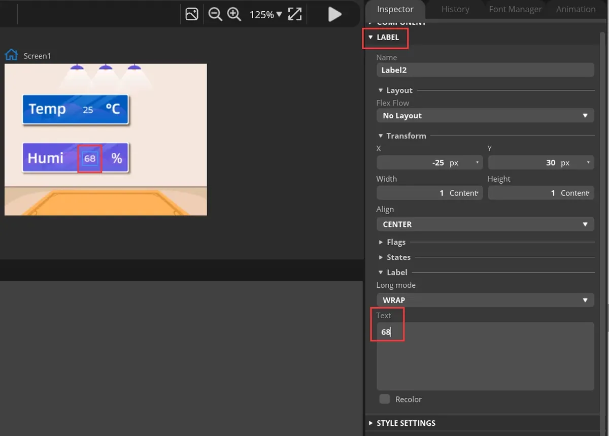
Select the two labels respectively and enter default numbers under Text for easy previewing. These are only design-time placeholder values and will be replaced by DHT20 readings once the development board is running.
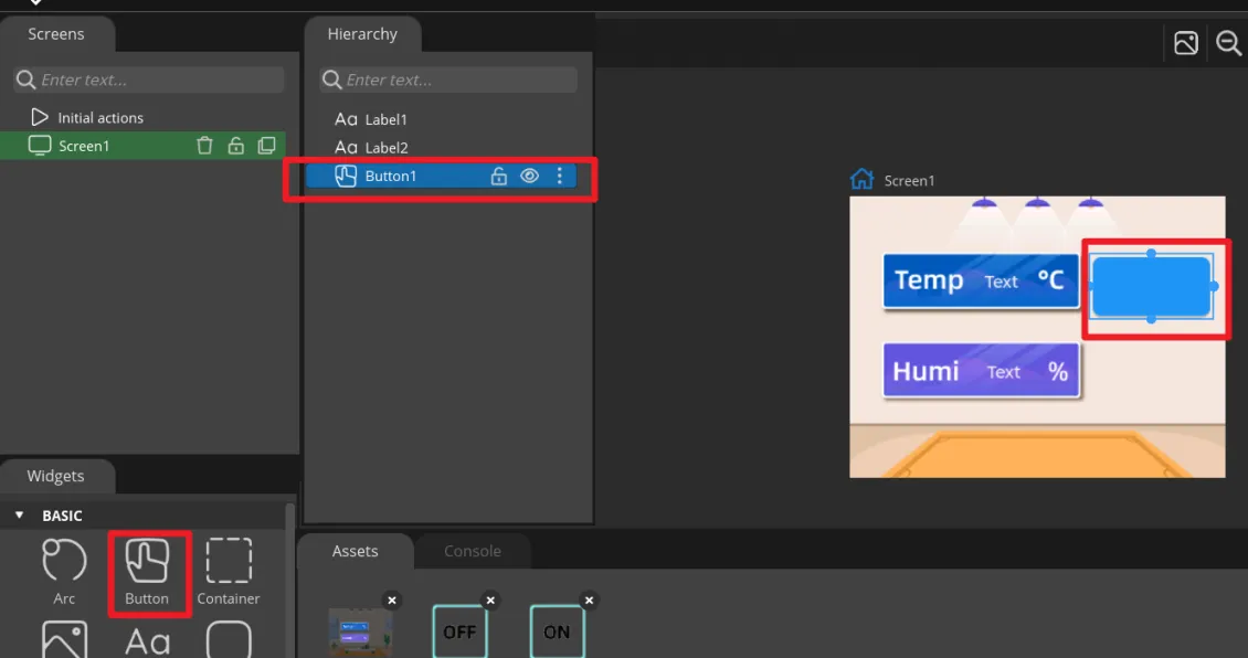
Click Button in the Widgets panel to add Button1, and drag it to the ON area on the right side of the interface.
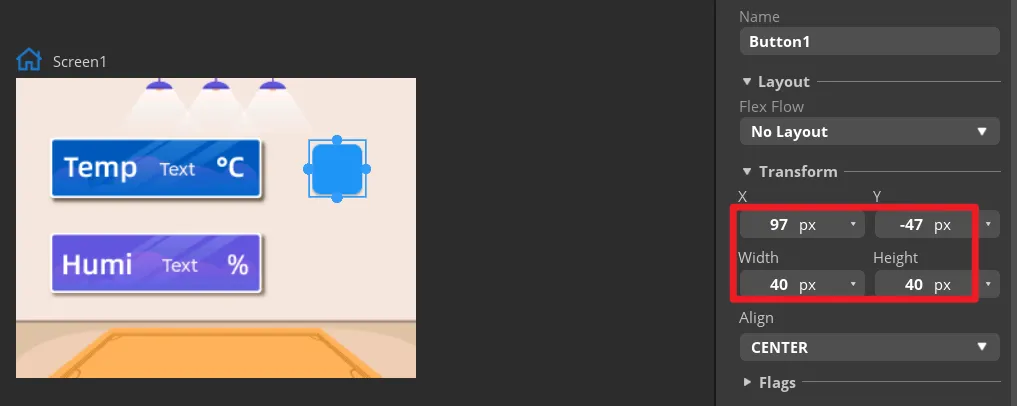
Set the size of Button1 under Transform and adjust its position so that the button aligns with the ON area in the background.
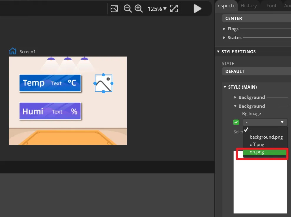
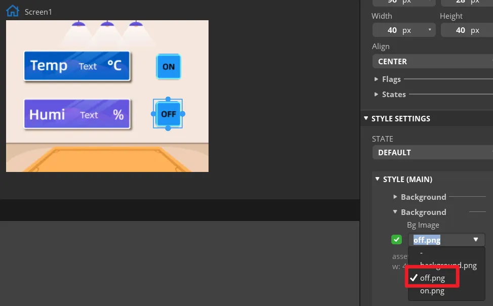
Expand STYLE (MAIN) > Background of Button1 and select on.png as the background image. The ON icon should appear on the canvas.
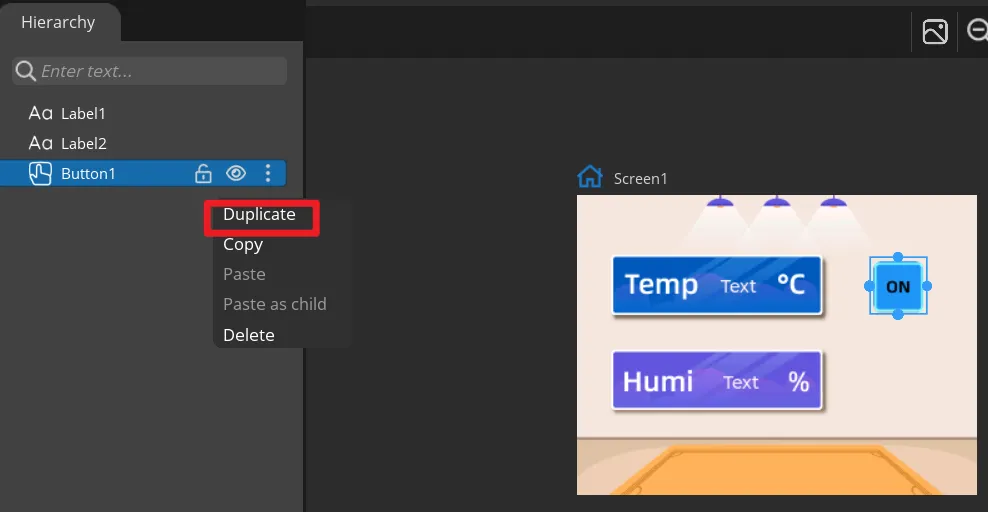
Duplicate Button1 to get Button2, move it to the OFF area, and change its background image to off.png. Keep the names Button1 and Button2 to make them correspond to the exported event functions.
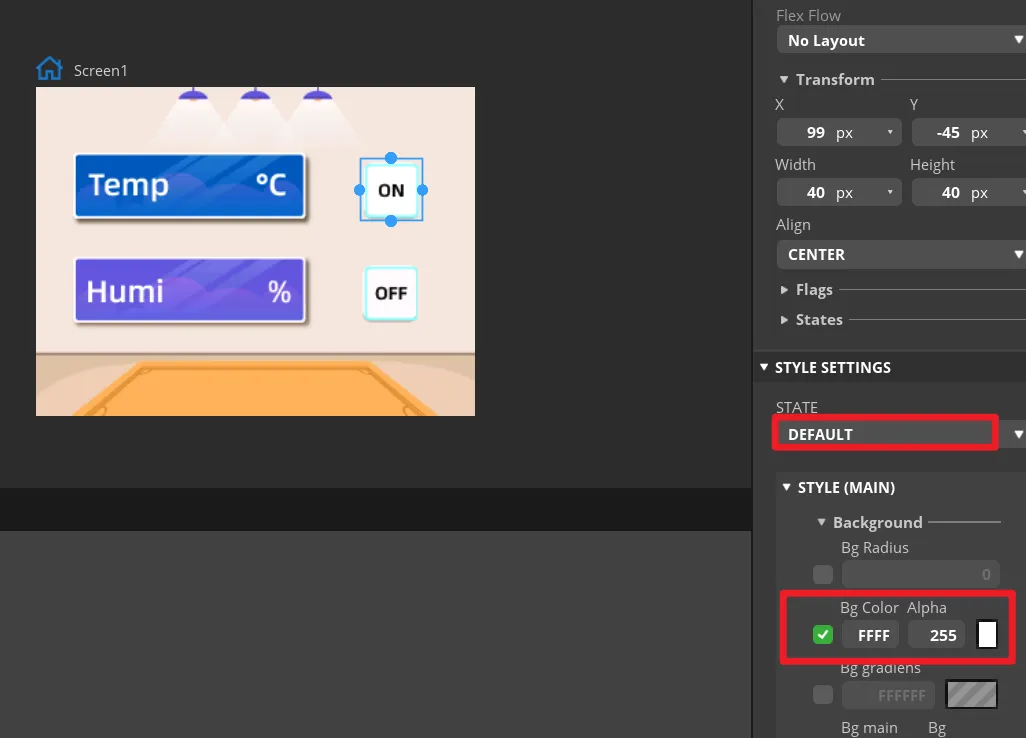
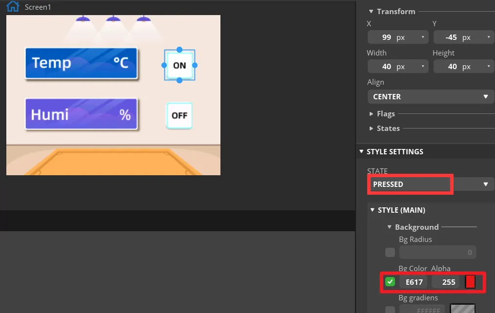
Under the STATE settings of both buttons, check the DEFAULT and PRESSED states. The pressed state may use an obvious color change so that you can tell whether a button is pressed during preview. In "Inspector" -> "Style Settings" -> "State", set the displayed background color to white, while it shows red when in the "Checked" state. Set the same parameters for the "OFF" button.
Select Button1 and click ADD EVENT
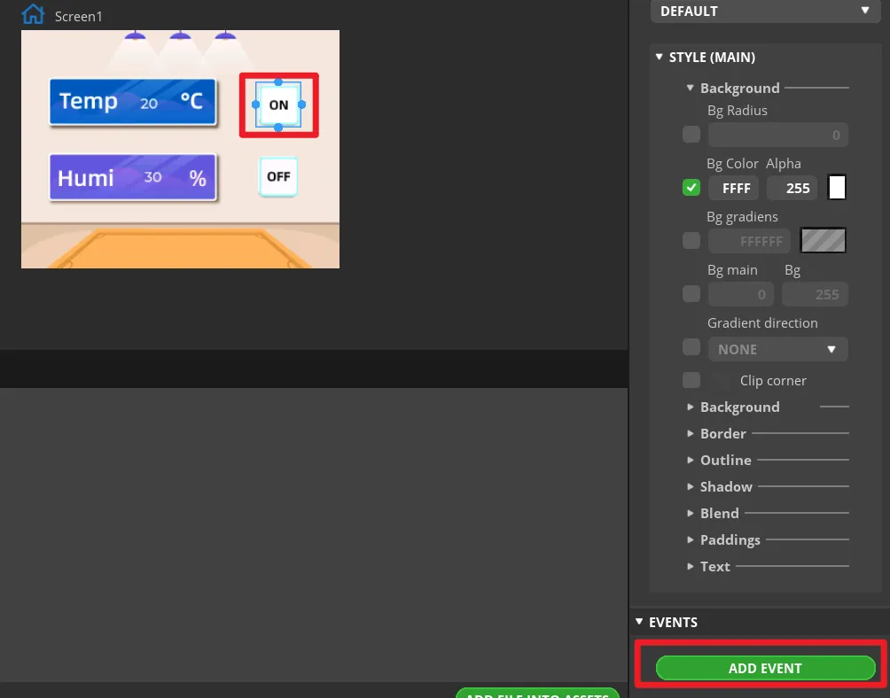
Select "CLICKED" as the trigger condition and choose the trigger event under "Action". The LED control function will be implemented by modifying the generated program later.
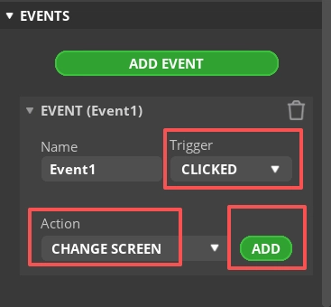
Notes: Since the button ultimately controls the LED on/off, you can add any event here first to let the exported UI files generate the button event code framework; the LED control code will be modified in a later step.
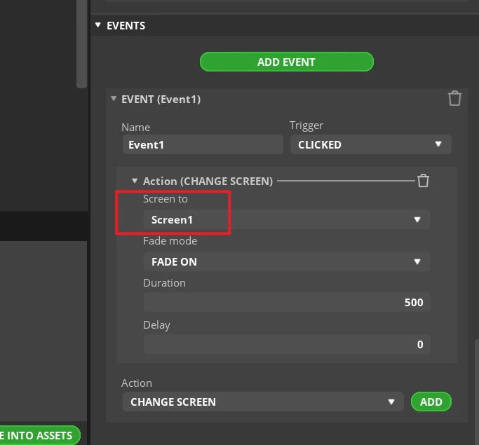
Complete this event. Here, I choose to switch screens, that is, switch to the Screen1 screen.
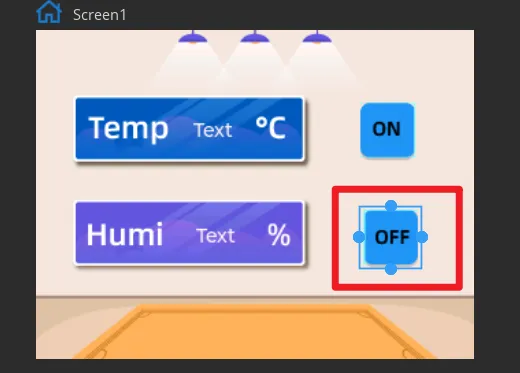
Add the event to Button2 in the same way (the state is "OFF").
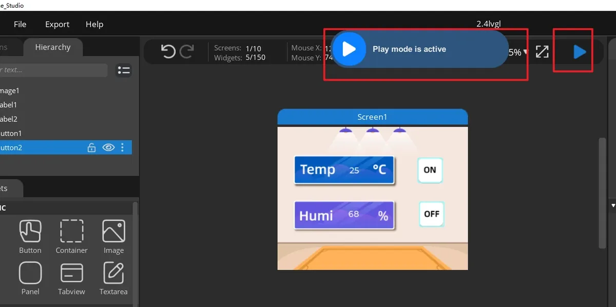
Click Run.
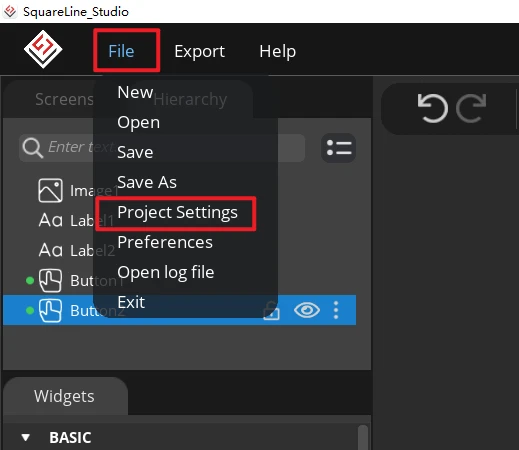
Open File > Project Settings, then configure the relevant settings for the exported files.
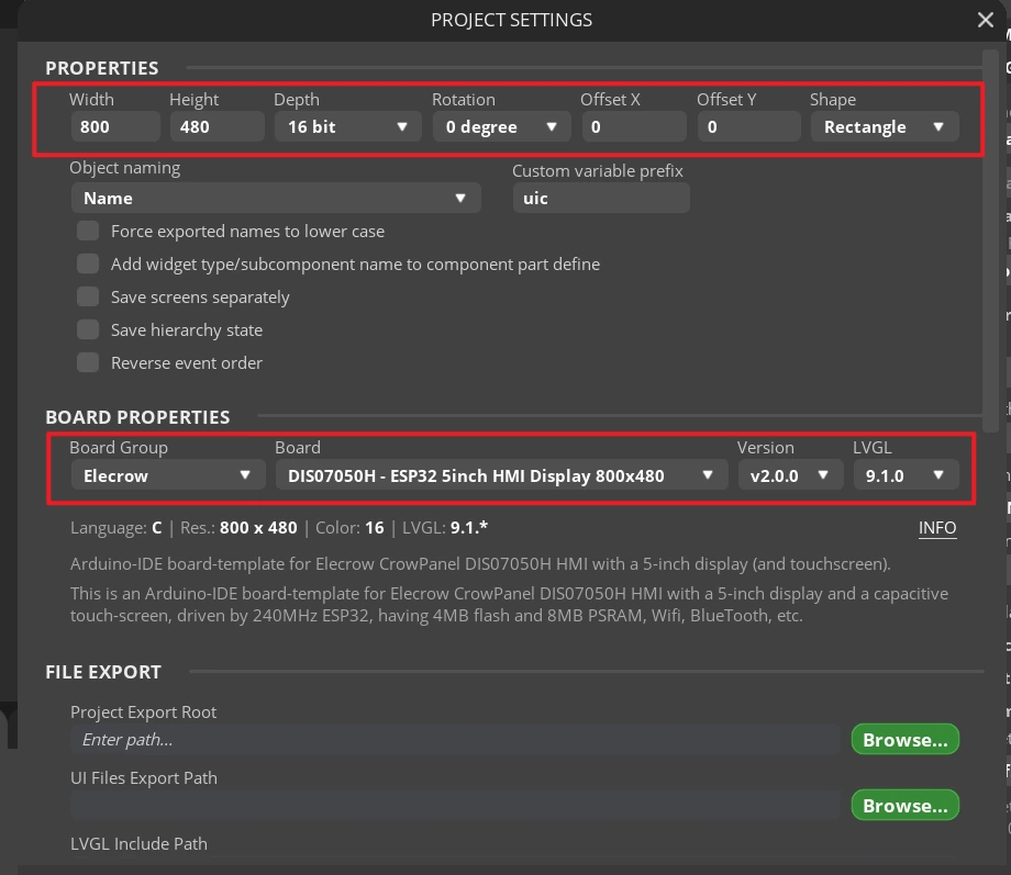
Set the export directory to an easy-to-find path using English characters only, create a new output folder, confirm that the LVGL Include Path is lvgl.h, and click APPLY CHANGES after confirmation.
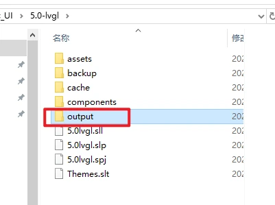
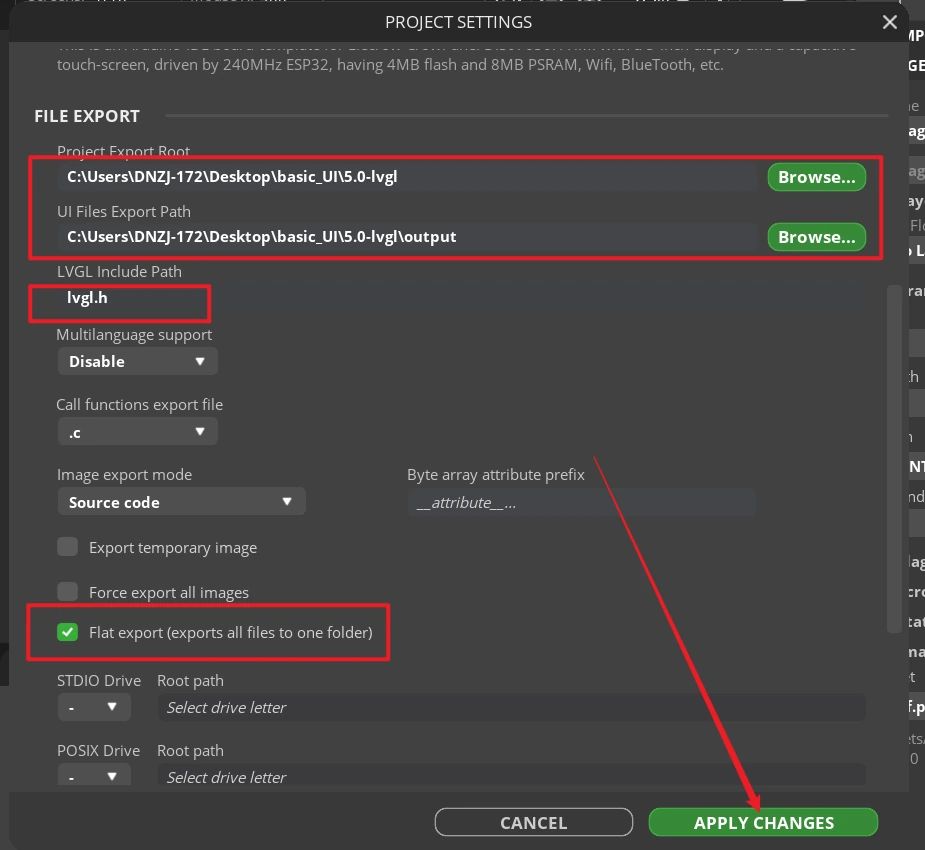
Tip: After selecting Flat export, all output files are placed in the same folder, so the program does not need to modify file paths. If Flat export is not selected, the files are scattered across different folders and the compiler may not recognize them automatically, usually requiring manual path modifications, so it is recommended to keep it checked.
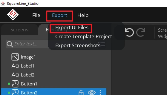
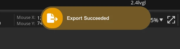
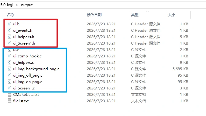
Click Export > Export UI Files. Once the export is complete, ui.c, ui.h, ui_Screen1.c, the event files, helper files, and the image array file should appear in the target directory.
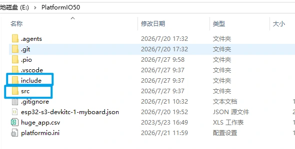
Add the UI files to the PlatformIO project. We need to add the UI files from SquareLine Studio to the PlatformIO project. The .c files from the UI should be placed in the project's /src folder, while the .h files should be placed in the /include folder.
8. Experimental Results
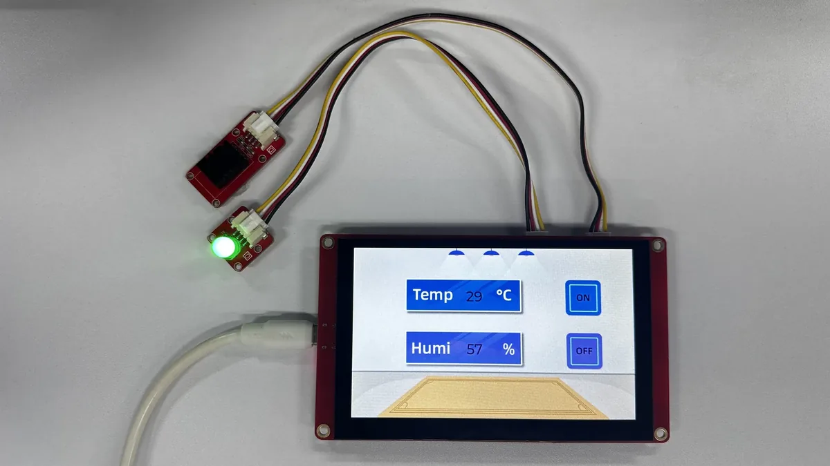
After the firmware is uploaded and the board is reset, the LCD is first cleared to black, and about 300 ms later the backlight turns on and loads the 800×480 UI. The background image should display completely, with two white integers shown slightly left of center on the screen and ON and OFF icons shown on the right. When the DHT20 is properly connected, the two integers update according to the temperature and humidity readings, respectively.
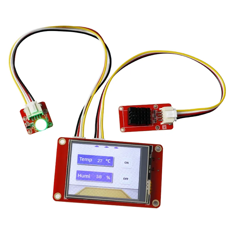
After clicking ON, the LED corresponding to GPIO38 lights up.
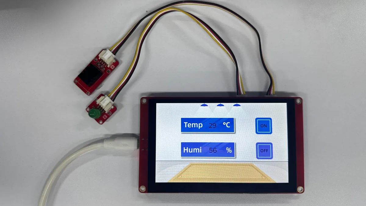
After clicking OFF, it turns off.
9. Code Download
- PlatformIO project: PlatformIO50.