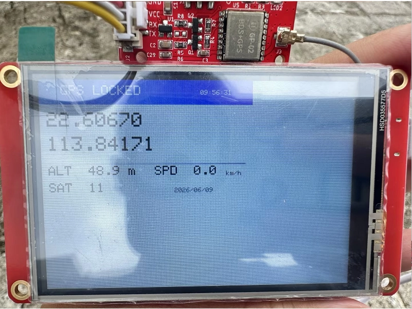
LVGL_Arduino3.5: 3.5-inch ESP32 Touchscreen Environment Monitoring and LED Control
1. Course Introduction
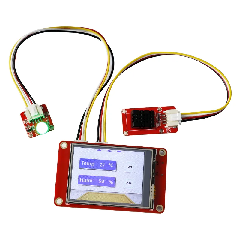
This lesson uses Arduino IDE 2.3.10 and Arduino-ESP32 3.3.8 to drive a 3.5-inch ESP32 touchscreen. Together with TFT_eSPI 2.5.43, LVGL 9.1.0, the DHT20, and the UI exported from SquareLine Studio 1.6.1, it implements temperature and humidity display and touch-controlled LED operation. After the program starts, the LCD backlight turns on and displays the background, two sensor readings, and the ON and OFF buttons. When a button is tapped, a UI event modifies the led state, and the main loop then controls GPIO25.
Learners need to complete board setup, project compilation, and upload, then observe the LCD, touch, LED, and serial output. At the end of the lesson, eight standalone examples are also provided—LED, OLED, speaker, SD card, touch, BLE, Wi-Fi, and GPS—so that onboard or external functions can be verified one by one.
Reference materials:
2. Learning Objectives
- Be able to select
ESP32-WROOM-DA Modulein Arduino IDE 2.3.10 and complete compilation and upload of the main project. - Be able to explain the data flow among the LVGL display flush callback, the touch input callback, TFT_eSPI, and the SquareLine UI.
- Be able to read DHT20 temperature and humidity and update the integer results to
ui_Label1andui_Label2. - Be able to change
ledthrough the ON/OFF buttons and verify that the GPIO25 output changes synchronously with the serial status. - Be able to determine whether the experiment is successful based on the backlight, UI, touch coordinates, sensor readings, and LED response.
3. What You Need to Prepare
- One 3.5-inch ESP32 touchscreen development board, with the target chip being ESP32.
- One USB data cable that supports both power supply and data transfer.
- One DHT20 temperature and humidity module, connected to GPIO22 (SDA) and GPIO21 (SCL).
- One LED module, connected to GPIO25; if using the board's interface label, connect it to the GPIO_D interface.
- Arduino-ESP32 3.3.8, with the board set to
ESP32-WROOM-DA Module. - Built-in project libraries: LVGL 9.1.0, TFT_eSPI 2.5.43, Crowbits_DHT20, and the complete SquareLine UI files from the main lesson directory.
- Keep the
ui*.c,ui*.h, and image array files in theLVGL_Arduino3.5directory intact; do not copy only the.inofile.
4. Software Operation Steps
This tutorial uses Arduino IDE 2.3.10 for demonstration. The IDE version is not strictly required, and other versions work as well.
For your first operation, please complete the steps in order; do not jump directly to uploading after a failed compilation.
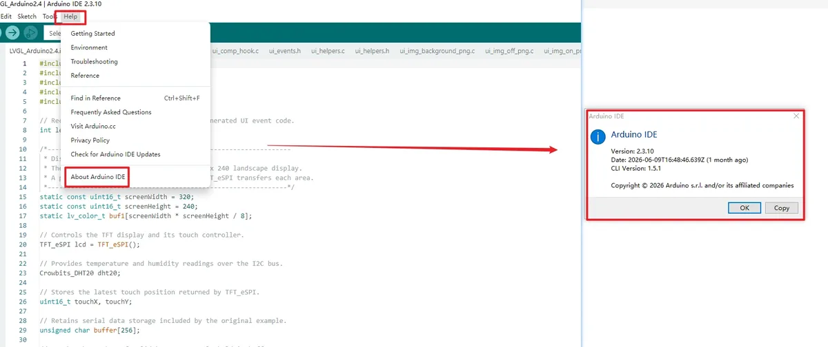
Launch Arduino IDE, open Help > About Arduino IDE, and confirm the version is 2.3.10. Close the About window before continuing.
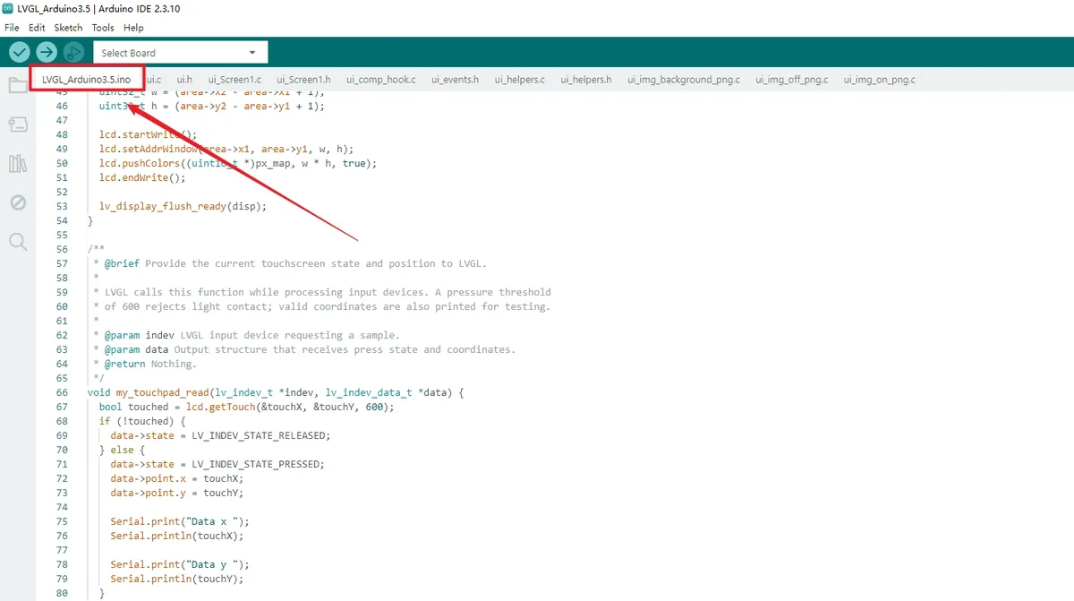
Select File > Open, navigate to the project folder LVGL_Arduino3.5, and open LVGL_Arduino3.5.ino. The window title should display the project name. 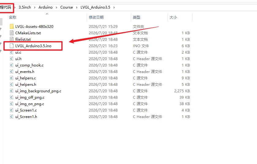
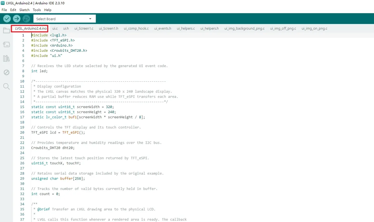
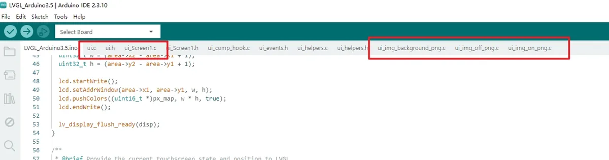
Check the file tabs above the editor area and confirm that ui.c, ui.h, ui_Screen1.c, and three ui_img_*_png.c files are visible in the same project. If any of these files are missing, do not continue compiling; instead, copy the complete project directory again.
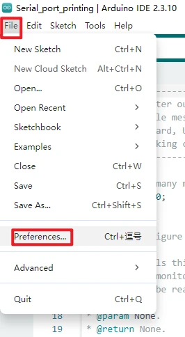
Open the Arduino IDE and go to File > Preferences.
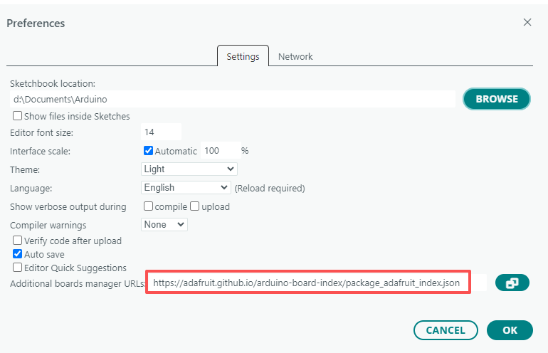
In Additional boards manager URLs, add the Espressif ESP32 board index address:
Remember to click confirm after making changes.
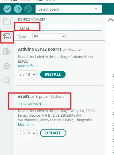
Open the Board Manager, search for esp32. Find esp32 by Espressif Systems, select it, and install 3.3.8; if the interface already shows 3.3.8 installed, simply close the Board Manager.
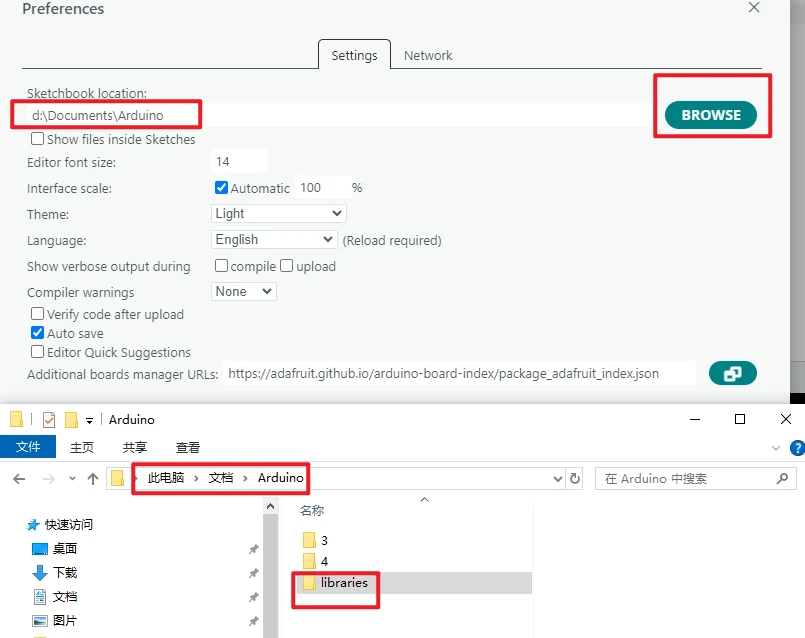
Open File > Preferences, and note down the "Sketchbook location". Close Arduino IDE, then confirm that a libraries folder exists in that directory.
How to add the library files: https://www.elecrow.com/wiki/Arduino_IDE_Library_Import_Guide.html.
Note: The course dependency libraries need to be placed in the libraries directory under the Arduino sketchbook folder. After copying is complete, restart Arduino IDE to prevent the IDE from still using the old library index.
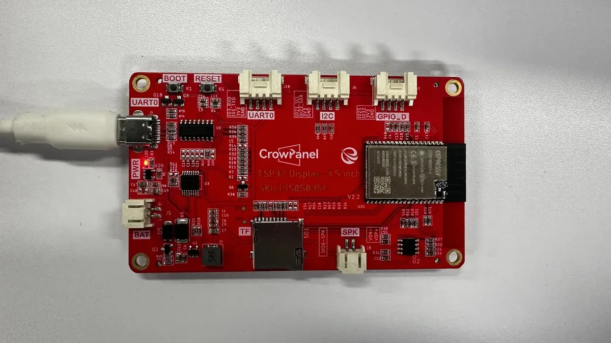
Connect the development board using the USB data cable.
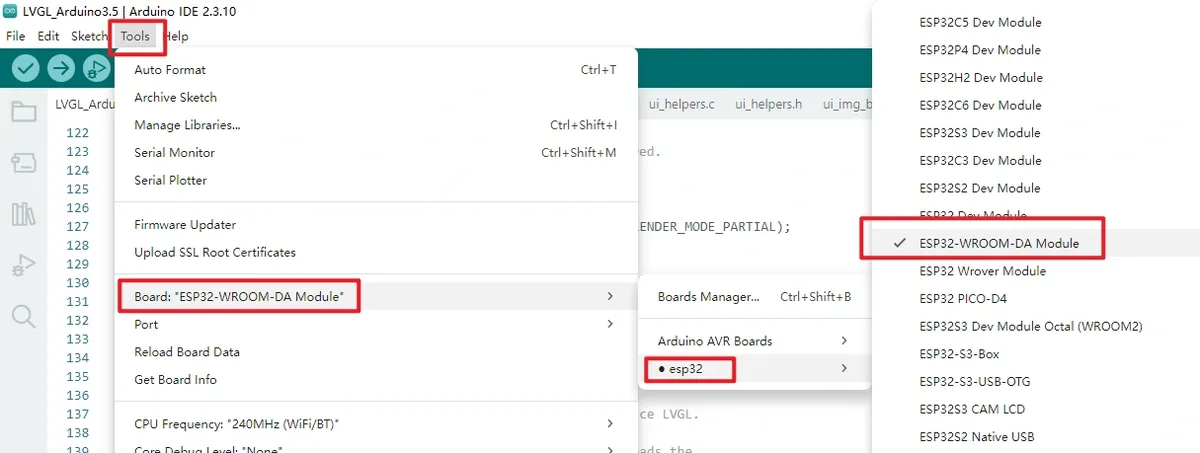
Open Tools > Board > esp32, and select ESP32-WROOM-DA Module. After completion, the IDE top bar or status bar should display this board name.
Open Tools > Port, and select the newly appeared COM port.
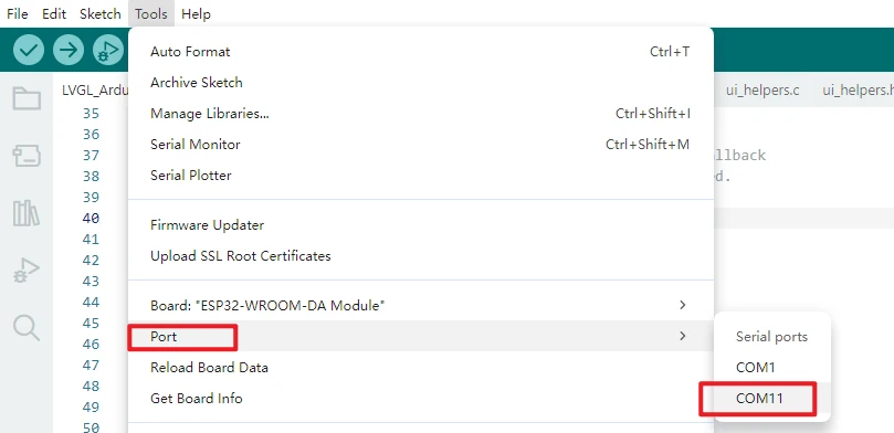
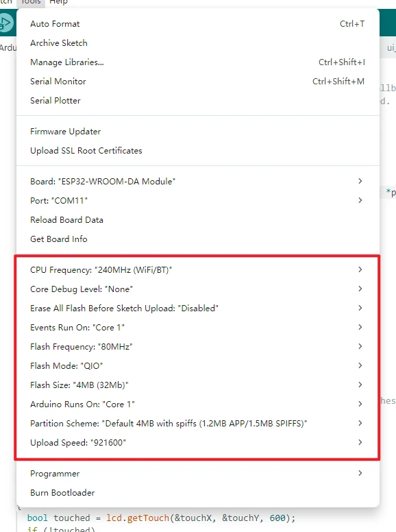
In the Tools menu, keep all other options at their default values.
Click the Upload button and wait for the output window to show the write progress and display the upload complete message. If it stays at Connecting... for a long time, hold down the board's BOOT button and release it once writing begins; if it still fails, recheck the port. 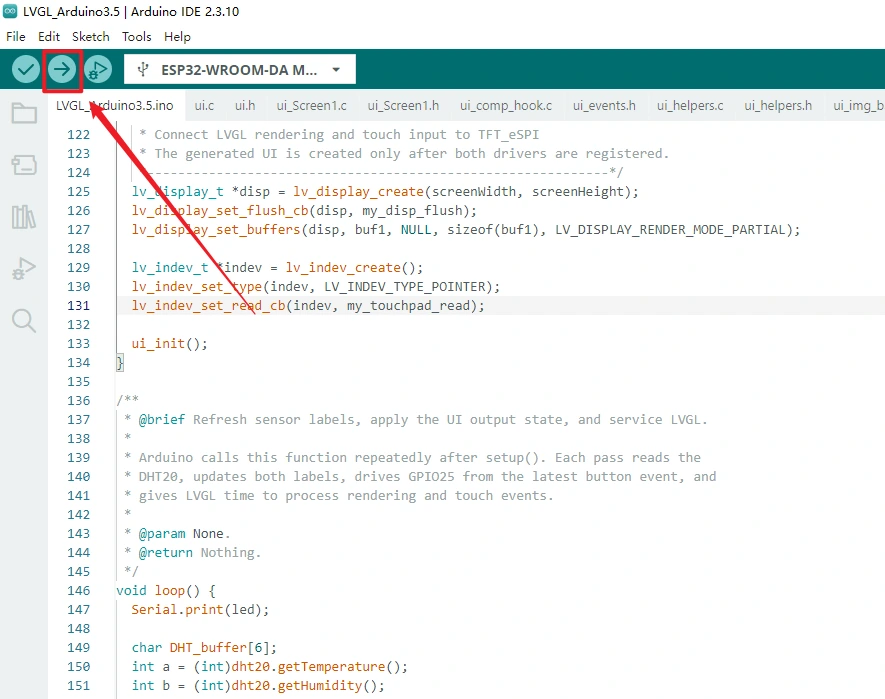
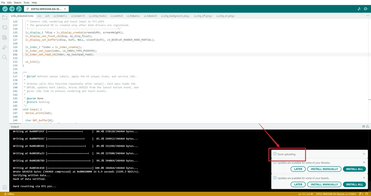
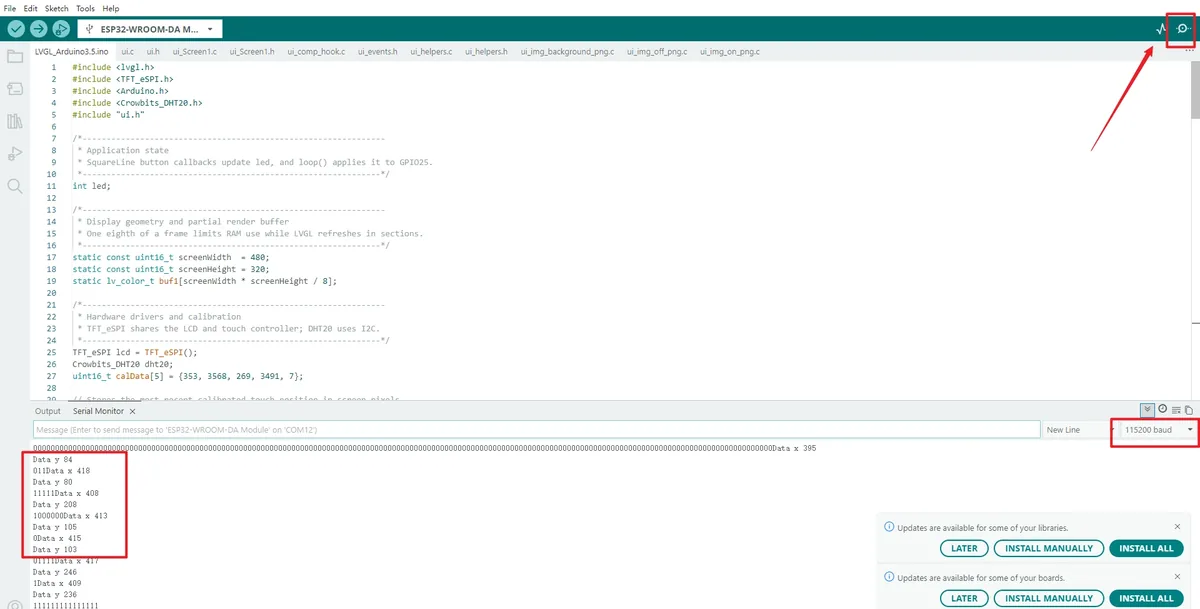
Click the Serial Monitor in the top-right corner and set the baud rate to 115200. When you touch the screen, Data x and Data y should appear; after clicking ON or OFF, the led value should also be shown.
5. Hardware Operation Steps
With the power off, connect the DHT20 module to the board's IIC interface, making sure SDA maps to GPIO22 and SCL maps to GPIO21. Connect the LED module to the interface labeled GPIO_D so that its signal line connects to IO25. Do not connect the signal line to a power pin, and do not hot-plug the module while powered.
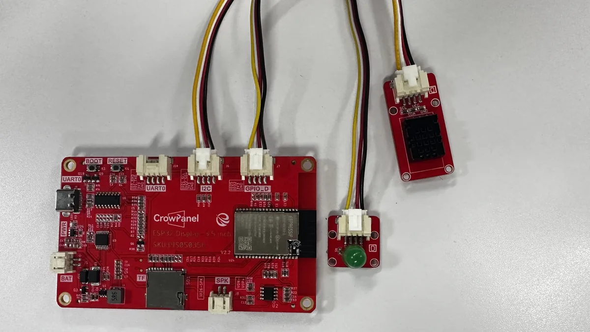
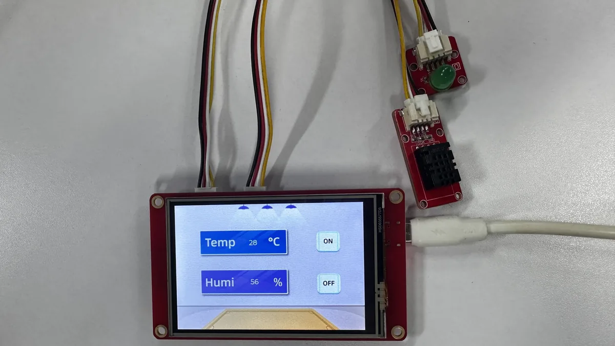
Reconnect the USB cable that supports data transfer. After the upload completes and the board auto-resets, the screen backlight should turn on, and the interface should show temperature, humidity, and the ON and OFF buttons.
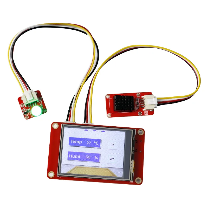
Tap ON and OFF in turn with your finger, and observe whether the LED lights up and turns off accordingly, while checking whether the serial monitor outputs the corresponding status. Do not press the screen with sharp or conductive objects.
ON -> LED lights up.
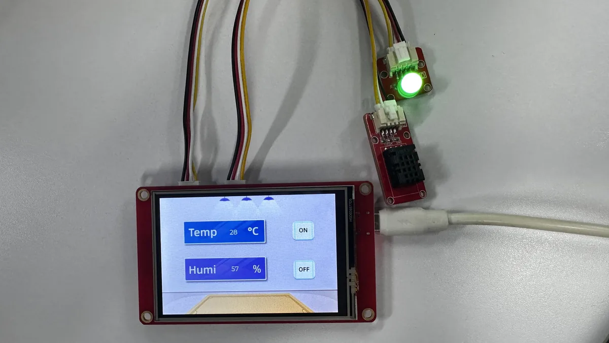
OFF -> LED turns off.
6. Key Code Explanation
6.1 LVGL Partial Refresh to the LCD
// Keep the display geometry and partial buffer consistent with the 480x320 panel.
static const uint16_t screenWidth = 480;
static const uint16_t screenHeight = 320;
static lv_color_t buf1[screenWidth * screenHeight / 8];

// Transfer each rendered rectangle from LVGL's buffer to the TFT_eSPI display.
void my_disp_flush(lv_display_t *disp, const lv_area_t *area, uint8_t *px_map)
{
  uint32_t w = (area->x2 - area->x1 + 1);
  uint32_t h = (area->y2 - area->y1 + 1);

  lcd.startWrite();
  lcd.setAddrWindow(area->x1, area->y1, w, h);
  lcd.pushColors((uint16_t *)px_map, w * h, true);
  lcd.endWrite();
  // Tell LVGL that the drawing buffer can be reused for the next area.
  lv_display_flush_ready(disp);
}
LVGL places only the rectangular region that needs updating into buf1, then calls my_disp_flush(). The area determines the LCD write window, and px_map is the 16-bit color data for that region. Finally, lv_display_flush_ready() tells LVGL that the buffer can be reused; if this is omitted, the interface usually freezes after the first refresh. The resolution must match the 480×320 display area in landscape orientation; otherwise, cropping or misalignment may occur.
6.2 Passing Touch State to LVGL
// Convert the calibrated touch sample into the state and coordinates LVGL expects.
void my_touchpad_read(lv_indev_t *indev, lv_indev_data_t *data)
{
  // A pressure threshold of 600 filters out light or unstable contact.
  bool touched = lcd.getTouch(&touchX, &touchY, 600);
  if (!touched) {
    data->state = LV_INDEV_STATE_RELEASED;
  } else {
    data->state = LV_INDEV_STATE_PRESSED;
    // Forward the valid screen coordinates to the pointer input device.
    data->point.x = touchX;
    data->point.y = touchY;
  }
}
LVGL calls this callback when processing input devices. 600 is the pressure threshold TFT_eSPI uses to accept touches; too high a threshold may miss touches, while too low may cause false triggers. Coordinates are updated only when in the pressed state. If the UI displays but buttons do not respond, first check whether lv_indev_set_read_cb() has registered this function, then check whether the serial monitor continuously outputs reasonable coordinates in the 0–479 and 0–319 ranges.
6.3 Registering the Display, Input Device, and UI
// Start LVGL before registering its display, input, and generated UI objects.
lv_init();
// Arduino's millisecond counter supplies LVGL's scheduler time base.
lv_tick_set_cb(millis);

lv_display_t *disp = lv_display_create(screenWidth, screenHeight);
lv_display_set_flush_cb(disp, my_disp_flush);
lv_display_set_buffers(disp, buf1, NULL, sizeof(buf1), LV_DISPLAY_RENDER_MODE_PARTIAL);

lv_indev_t *indev = lv_indev_create();
lv_indev_set_type(indev, LV_INDEV_TYPE_POINTER);
lv_indev_set_read_cb(indev, my_touchpad_read);

// Create the SquareLine Studio screen, labels, and ON/OFF buttons last.
ui_init();
This code runs in setup(). The LVGL time base, display callback, and input callback must be ready first, and only then can the page objects be created with ui_init(). If ui_init() is removed, the LCD and backlight may still work, but the background, labels, and buttons will not appear; if the flush callback is not registered, the LVGL objects are created in memory but the LCD cannot display them.
6.4 Temperature/Humidity Labels and LED Linkage
char DHT_buffer[6];
// Convert the sensor readings to text before updating the generated labels.
int a = (int)dht20.getTemperature();
int b = (int)dht20.getHumidity();
snprintf(DHT_buffer, sizeof(DHT_buffer), "%d", a);
lv_label_set_text(ui_Label1, DHT_buffer);
snprintf(DHT_buffer, sizeof(DHT_buffer), "%d", b);
lv_label_set_text(ui_Label2, DHT_buffer);

if (led == 1) {
  // The ON button callback sets led to 1, so enable the external LED.
  digitalWrite(25, HIGH);
}
if (led == 0) {
  // The OFF button callback sets led to 0, so disable the external LED.
  digitalWrite(25, LOW);
}

// Keep rendering, touch events, and button callbacks responsive.
lv_timer_handler();
delay(10);
The DHT20 floating-point readings are converted to integers and then to the strings the LVGL labels require. The SquareLine event code sets led to 1 or 0 respectively when ON/OFF is tapped, and the main loop controls GPIO25 accordingly. lv_timer_handler() must be called continuously; otherwise, buttons, redraws, and event handling will all stop. The current Arduino code reads the sensor once per loop iteration, which is the original project behavior; if the sensor is abnormal, the labels may show unreasonable values, and the I2C connection should be checked first.
7. UI Asset Creation and Integration
This section uses SquareLine Studio 1.6.1 to re-demonstrate how to create the interface. The operation steps and illustrations follow Elecrow's official SquareLine Studio tutorial. The lesson already provides the exported UI files, so beginners can first read this section to understand the workflow and then directly use the files in the project to compile. When creating a new project, you must select LVGL 9.1.0 and use a resolution of 480×320;
How to download SquareLine Studio: https://www.elecrow.com/wiki/Create_LVGL_UI_with_SquareLine_Studio.html.
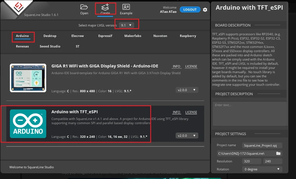
Launch SquareLine Studio 1.6.1, click Create, and select the Arduino with TFT_eSPI template for the Arduino platform. This template is responsible for generating the UI file framework suitable for Arduino and TFT_eSPI projects.
Note: When the Arduino framework is selected, SquareLine Studio shows only the Arduino with TFT_eSPI option. It generates template code suitable for TFT_eSPI, but SquareLine Studio also supports other graphics libraries; when switching to other hardware, you need to modify the display code according to the actual library.
Enter the project name, set the LVGL version to 9.1.0, the resolution to width 480 and height 320, and the color depth to 16 bit, then click CREATE. After creation, the canvas should be a landscape 480×320.
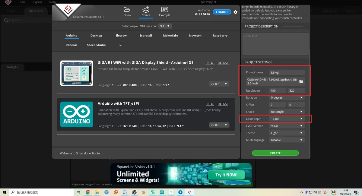
- Note: A
16 bitcolor depth can represent 65,536 colors using the RGB 5:6:5 pixel format. Keep it consistent with the project's color configuration.
After the project opens, select Screen1 in the Screens panel on the left, and confirm that the central canvas is blank and that the Inspector on the right shows the Screen properties. All subsequent widgets are added to this page.
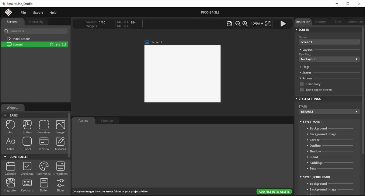
In the Assets area, click ADD FILE TO ASSETS, and import background.png, on.png, and off.png from LVGL-Assets-480x320/ in sequence. After importing, you should see three thumbnails.
Material link:
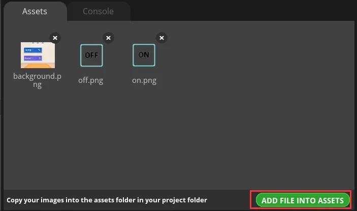
Note: Image assets only support the PNG format; the pixel size of an image should be smaller than the project's screen size; a single image should not exceed 100 KB, and preferably be kept within 30 KB, to avoid affecting display smoothness.
Select Screen1, expand STYLE SETTINGS > STYLE (MAIN) > Background on the right, and enable the background image setting.
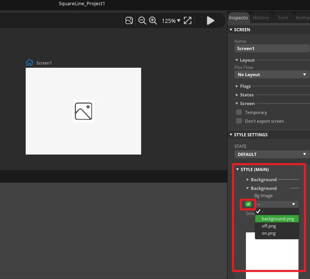
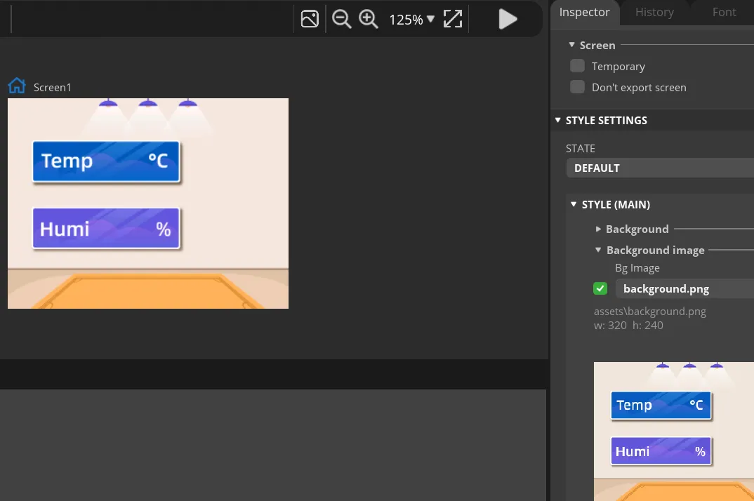
In Bg Image, select background. The canvas should immediately display the course background image, and the background should fully cover the 480×320 page.
In the Widgets panel on the left, click Label to add Label1 to Screen1. This label will be updated by the program to the temperature value.
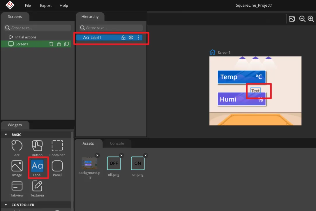
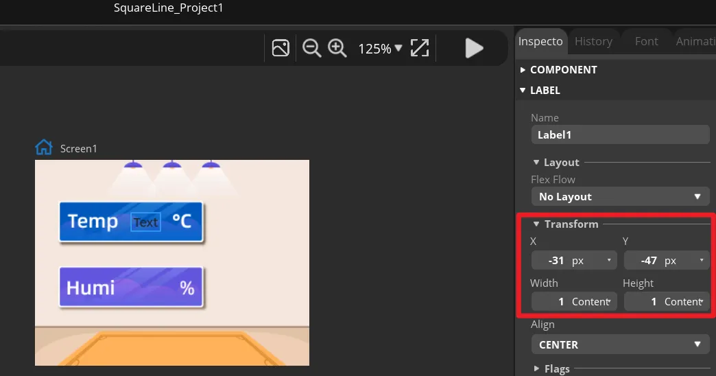
Select Label1, and in Transform adjust the X and Y position and the width and height so that it sits in the temperature display area of the background image. You can also drag it first and then fine-tune with numeric values.
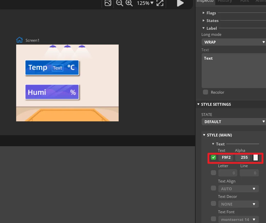
In Label1's STYLE (MAIN), change the text color to white and set an appropriate font size. The text on the canvas should be clearly visible and should not exceed the background frame.
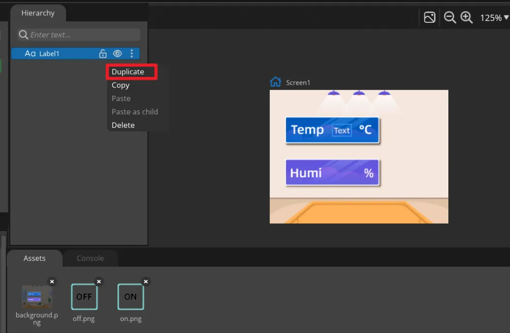
Right-click Label1 and select Duplicate to generate Label2, then move it to the humidity display area. Keep the names Label1 and Label2, because the main program updates them by name.
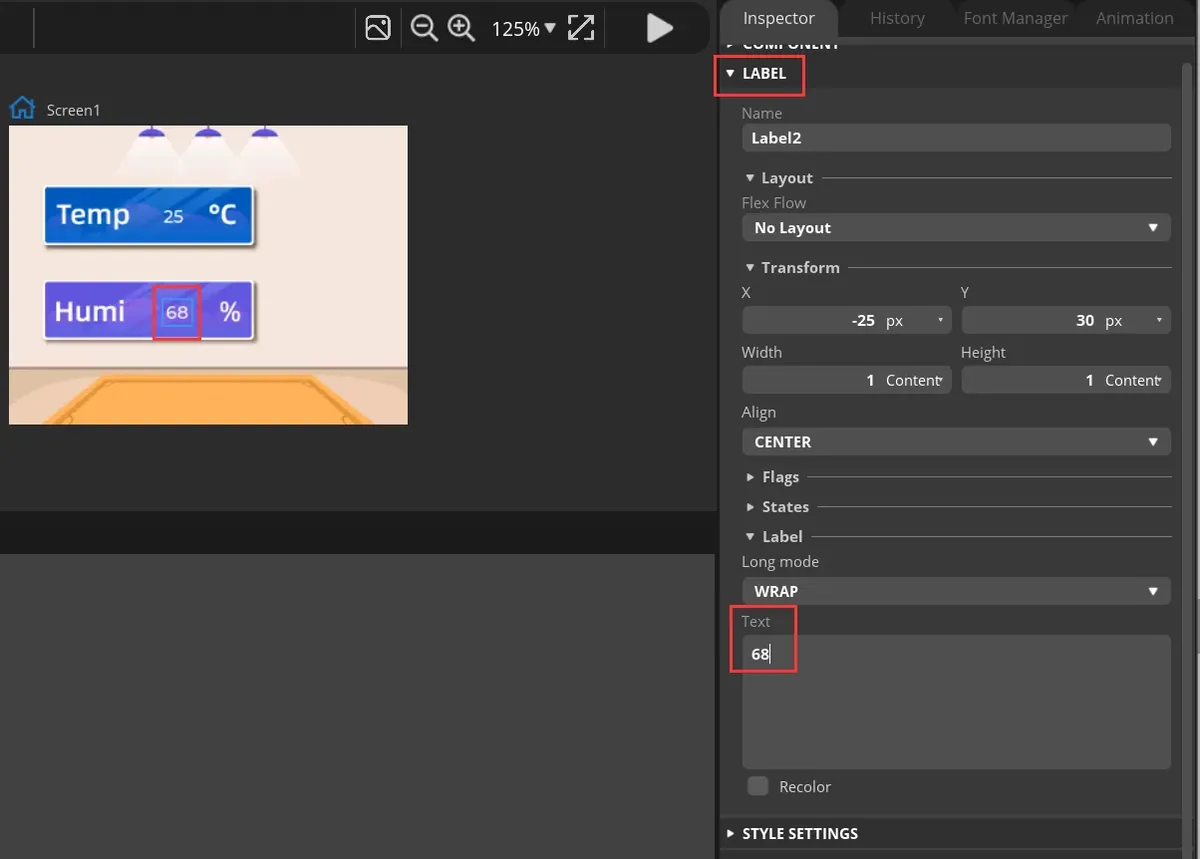
Select the two Labels respectively, and enter default numbers in Text for easy previewing. These are only design-time placeholder values and will be replaced by DHT20 readings once the board runs.
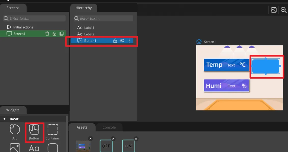
In Widgets, click Button to add Button1, and drag it to the ON area on the right side of the interface.
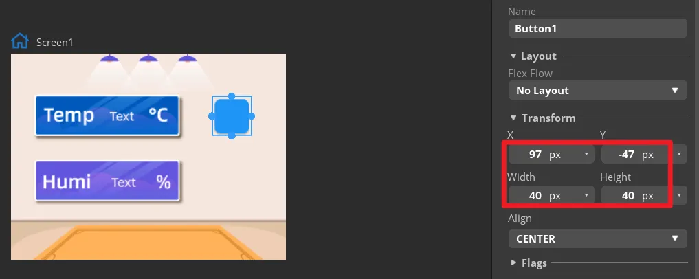
In Transform, set the size of Button1 and adjust its position so that the button aligns with the ON area in the background.
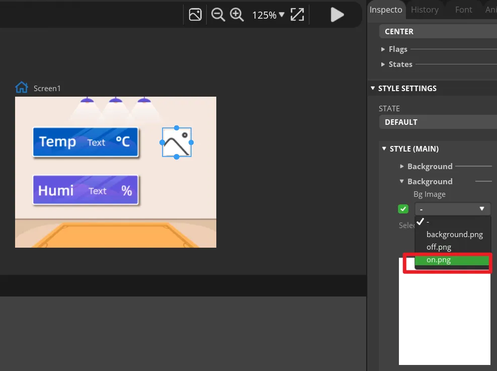
Expand Button1's STYLE (MAIN) > Background and select on. Usepng` as the background image. The ON icon should appear on the canvas.
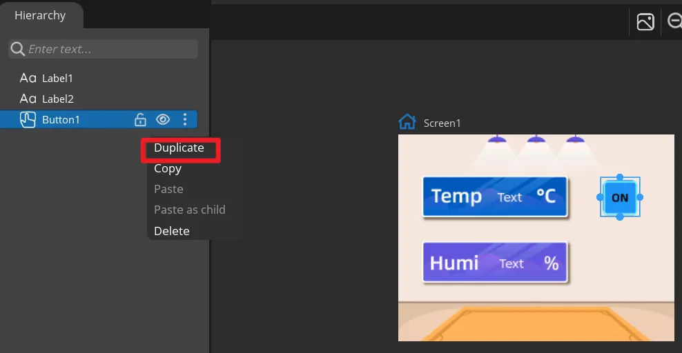
Duplicate Button1 to create Button2, move it to the OFF area, and change the background image to off.png. Keep the names Button1 and Button2 so they correspond to the exported event functions.
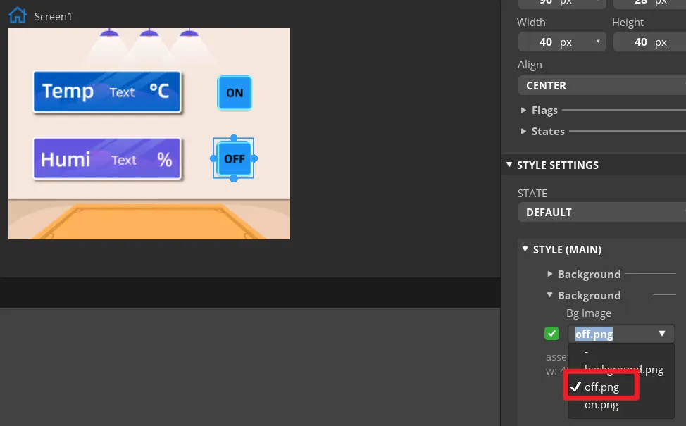
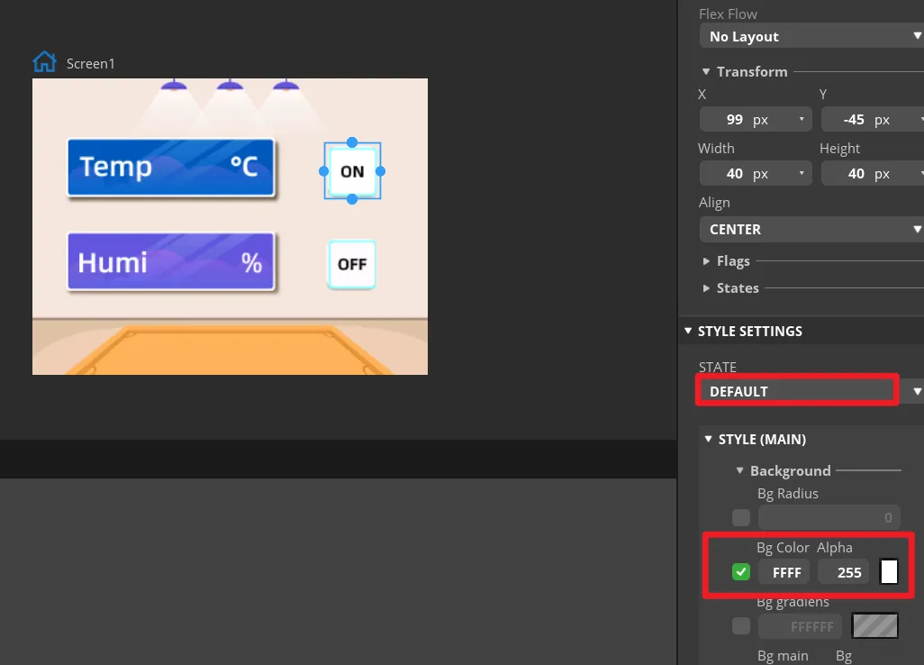
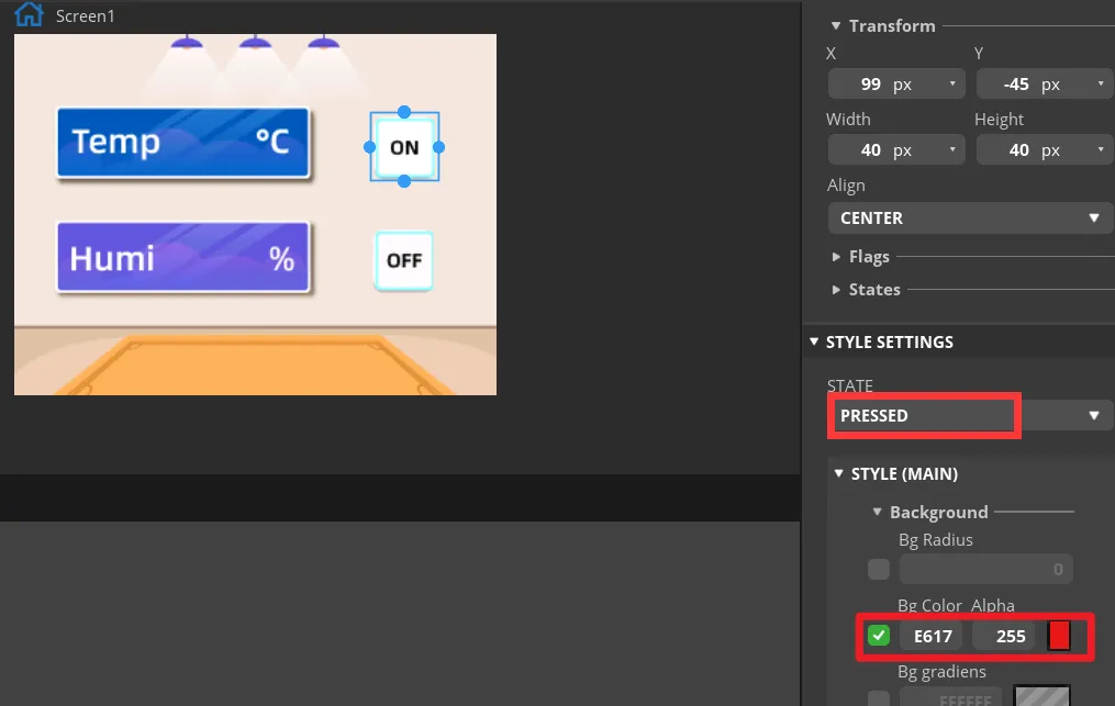
In the STATE settings of both buttons, check the DEFAULT and PRESSED states. For the pressed state, use an obvious color change so you can tell whether a button is pressed during preview. In "Inspector" → "Style Settings" → "State", set the displayed background color to white, and show red when in the "Fixed State". Set the same parameters for the OFF button.
Select Button1 and click ADD EVENT.
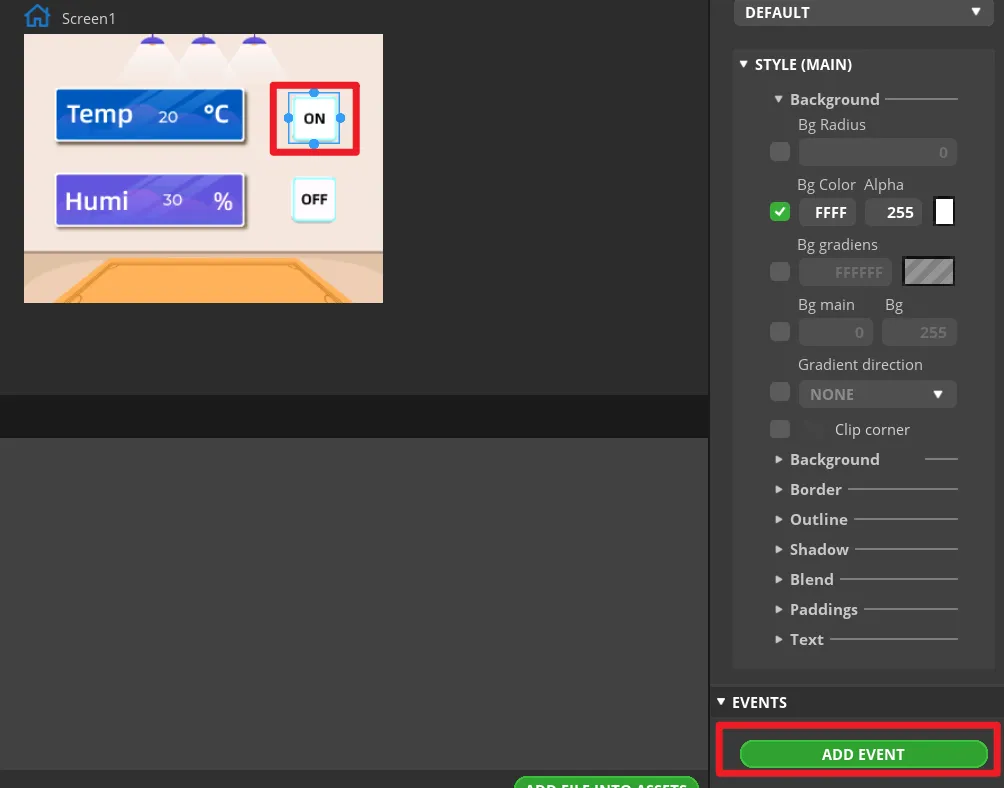
Select "CLICKED" as the trigger condition, and choose the trigger event in "Action". The generated program will be modified later to implement LED control.
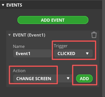
Note: Because the button ultimately controls the LED on/off, you can add any event here first so that the exported UI file generates the button event code framework; the LED control code will be modified in a later step.
Complete this event. Here, I choose to switch screens, that is, switch to the Screen1 screen.
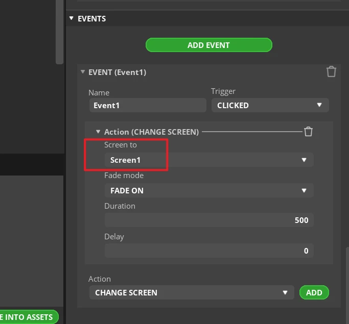
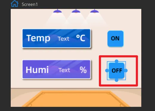
Add the event to Button2 in the same way (its state is "OFF").
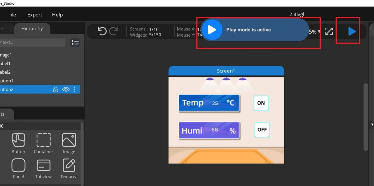
Click Run.
Open File > Project Settings, then configure the relevant settings for the exported files.
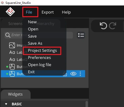
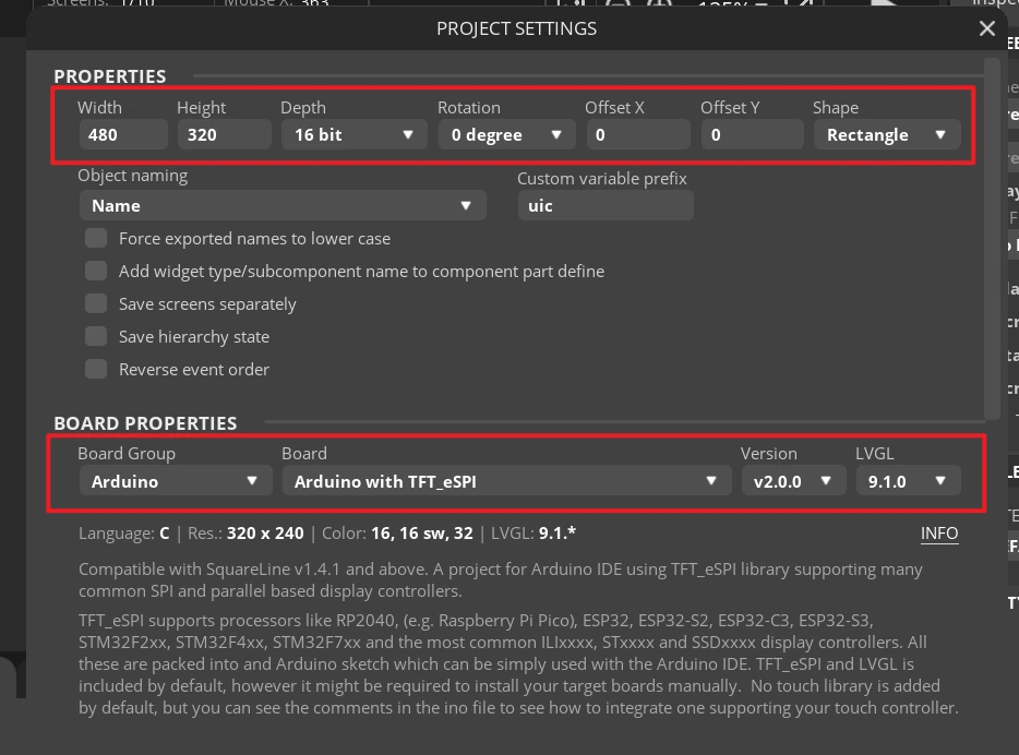
Set the export directory to an easy-to-find pure-English path, create a new output folder, fill in and confirm that the LVGL Include Path is lvgl.h, then click APPLY CHANGES after confirmation.
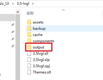

Tip: After selecting Flat export, all output files are placed in the same folder, and the program does not need to modify file paths. If Flat export is not selected, files are scattered across different folders, and the compiler may not recognize them automatically; you usually have to modify the paths manually, so it is recommended to keep it checked.
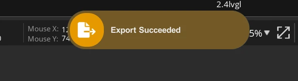
Click Export > Export UI Files. After the export is complete, ui.c, ui.h, ui_Screen1.c, the event file, helper files, and the image array file should appear in the target directory.
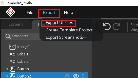
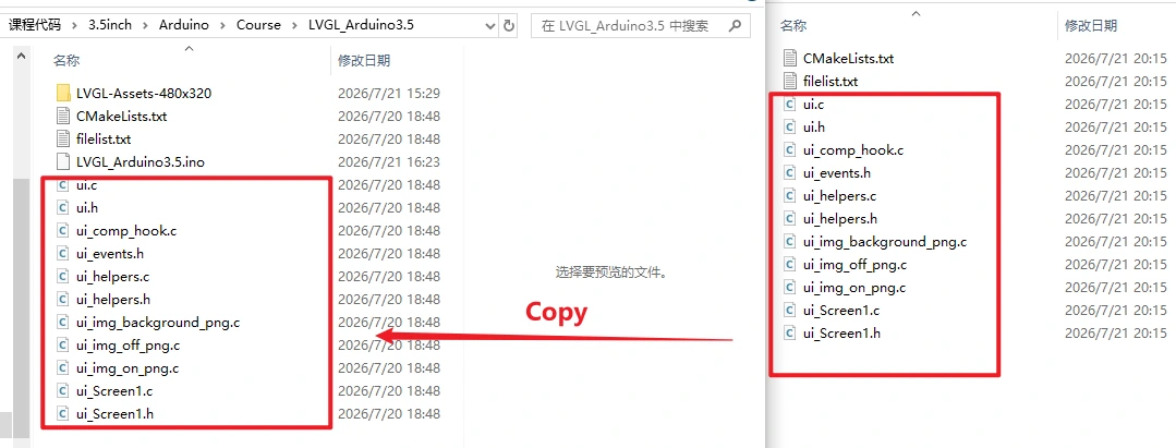
Close the Arduino IDE and copy all exported .c and .h files to the directory where LVGL_Arduino3.5.ino is located.
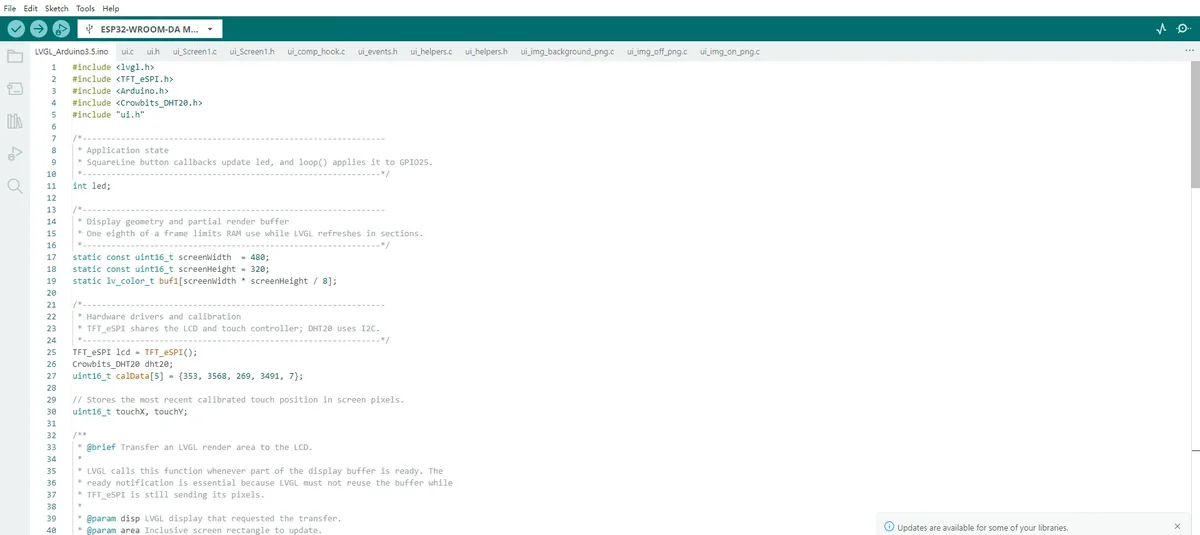
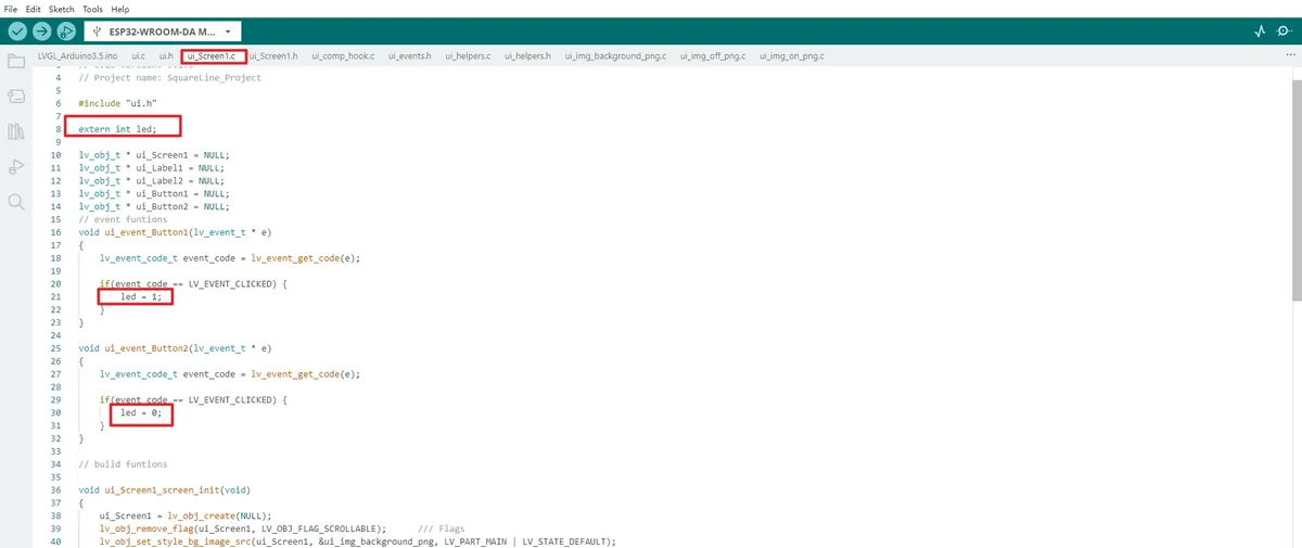
Reopen the project. In the two button event functions of ui_Screen1.c, keep the event type check, and make the ON event execute led = 1; and the OFF event execute led = 0;. Then return to the main program and click Verify to confirm there are no errors about led or UI objects not being found.
Then, replace the function calls in the Button1 and Button2 functions with the functions used to turn the LED on and off.
The ui_Screen1.c in the project ultimately creates two white numeric labels and two image buttons. If you modify the control name or resource name in SquareLine Studio, you must synchronously check the ui.h declaration, the ui_Screen1.c reference, and the ui_Label1 and ui_Label2 in the main program.
8. Experimental Observations
After the firmware is uploaded and reset, the LCD is first cleared to black, and about 300 ms later the backlight turns on and loads the 480×320 UI. The background image should be displayed in full, with two white integers shown slightly left of center, and the ON and OFF icons shown on the right. When the DHT20 is connected properly, the two integers update following the temperature and humidity readings respectively.
When you press the screen with your finger, the serial monitor outputs coordinates as Data x and Data y. After clicking the ON icon, led becomes 1, GPIO25 outputs a high level, and the serial port shows led_on; after clicking the OFF icon, led becomes 0, GPIO25 outputs a low level, and the serial port shows led_off. During continuous touch, the interface should remain responsive, and the device should not reset or freeze.
9. Code Download
Example Demo of ESP32 HMI Function
Example1: LED blinking.
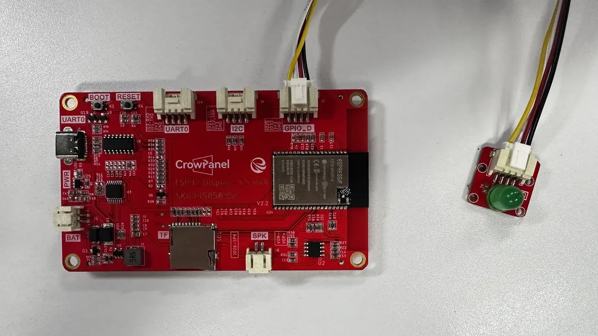
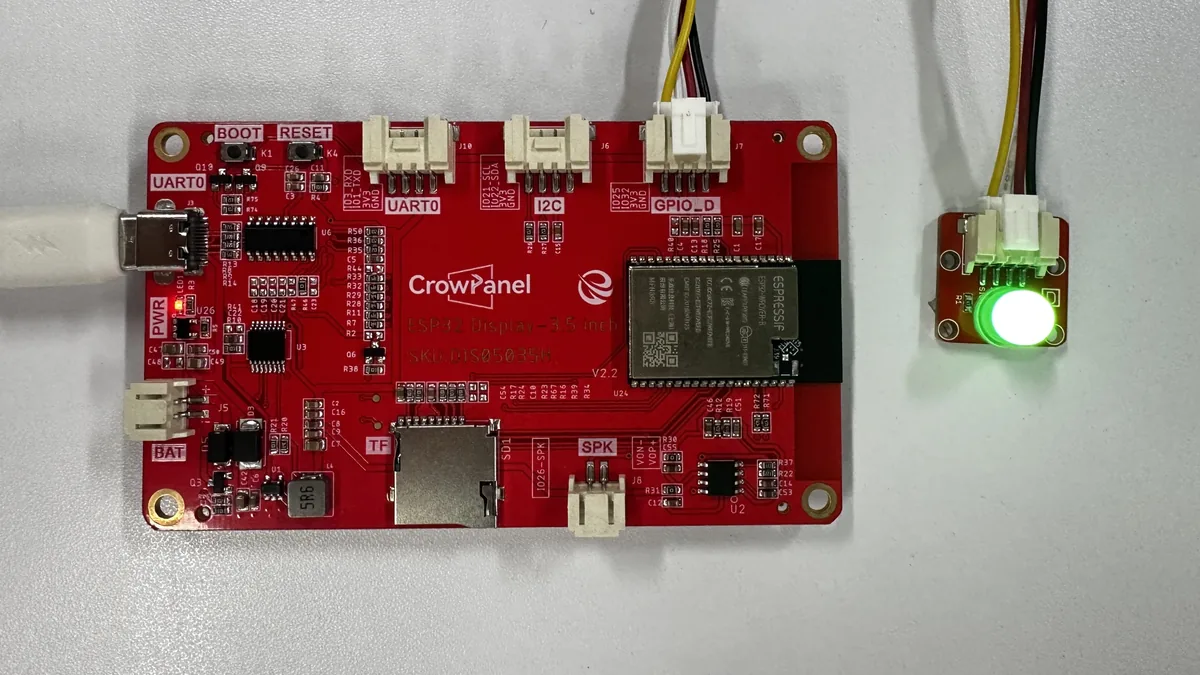
Connect the LED to the GPIO_D(IO25) port, and upload the following code to the board. The LED will blink.
Operation Tip: Power off first, connect the LED to the GPIO_D (IO25) port, then upload this example.
/*---------------------------------------------------------------
 * LED output configuration
 * GPIO25 drives the onboard indicator used by this example.
 *--------------------------------------------------------------*/
#define D_PIN 25

/**
 * @brief Prepare the serial port and LED output.
 *
 * Arduino calls this function once after power-up or reset. The pin must be
 * configured as an output before the repeating blink sequence starts.
 *
 * @param None.
 * @return Nothing.
 */
void setup() {
  Serial.begin(115200);
  pinMode(D_PIN, OUTPUT);
}

/**
 * @brief Blink the LED with equal on and off intervals.
 *
 * Arduino calls this function repeatedly after setup(). Each complete cycle
 * keeps the LED on for 500 ms and off for 500 ms.
 *
 * @param None.
 * @return Nothing.
 */
void loop() {
  digitalWrite(D_PIN, HIGH);
  delay(500);
  digitalWrite(D_PIN, LOW);
  delay(500);
}
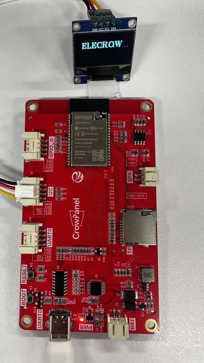
Example2: Control an external OLED screen through I2C.
Connect the OLED screen to the IIC port.
#include <U8g2lib.h>
#include <Wire.h>

/*---------------------------------------------------------------
 * OLED bus and display configuration
 * The software I2C instance uses the board's SDA and SCL pins.
 *--------------------------------------------------------------*/
#define I2C_SDA 22
#define I2C_SCL 21

// Provides drawing and page-buffer control for the 128 x 64 SSD1306 OLED.
U8G2_SSD1306_128X64_NONAME_F_SW_I2C u8g2(U8G2_R0, /*clock=*/I2C_SCL, /*data=*/I2C_SDA, /*reset=*/U8X8_PIN_NONE);

/**
 * @brief Initialize the OLED and scroll the ELECROW text across the screen.
 *
 * Arduino calls this function once after power-up or reset. U8g2 redraws the
 * full page for each horizontal position so the text appears to move left.
 *
 * @param None.
 * @return Nothing.
 */
void setup() {
  Serial.begin(115200);
  u8g2.begin();
  u8g2.enableUTF8Print();
  u8g2.setFont(u8g2_font_ncenB14_tr);
  u8g2.setFontDirection(0);

  /*-------------------------------------------------------------
   * Render the scrolling title
   * Move the starting x-coordinate left by 20 pixels per frame.
   *------------------------------------------------------------*/
  for (int i = 128; i > -78; i -= 20) {
    u8g2.firstPage();
    do {
      u8g2.drawStr(i, 25, "ELECROW");
      delay(2);
    } while (u8g2.nextPage());
  }
}

/**
 * @brief Leave the final OLED frame unchanged.
 *
 * Arduino calls this function repeatedly after setup(). The animation is a
 * one-shot startup demonstration, so no recurring work is required.
 *
 * @param None.
 * @return Nothing.
 */
void loop() {
}
Example3: Speaker
#include <driver/dac.h>

/*---------------------------------------------------------------
 * Speaker output configuration
 * GPIO26 is the physical output for ESP32 DAC channel 2.
 *--------------------------------------------------------------*/
#define SPEAKER_PIN 26

/*---------------------------------------------------------------
 * Sine-wave samples
 * One cycle contains 256 unsigned 8-bit DAC levels from 0 to 255.
 *--------------------------------------------------------------*/
const uint8_t sineWave[256] = {
  128, 131, 134, 137, 140, 143, 146, 149, 152, 155, 158, 161, 164, 167, 170, 173,
  176, 179, 182, 185, 187, 190, 193, 195, 198, 201, 203, 206, 208, 210, 213, 215,
  217, 219, 222, 224, 226, 228, 230, 231, 233, 235, 236, 238, 240, 241, 242, 244,
  245, 246, 247, 248, 249, 250, 251, 251, 252, 253, 253, 254, 254, 254, 254, 254,
  255, 254, 254, 254, 254, 254, 253, 253, 252, 251, 251, 250, 249, 248, 247, 246,
  245, 244, 242, 241, 240, 238, 236, 235, 233, 231, 230, 228, 226, 224, 222, 219,
  217, 215, 213, 210, 208, 206, 203, 201, 198, 195, 193, 190, 187, 185, 182, 179,
  176, 173, 170, 167, 164, 161, 158, 155, 152, 149, 146, 143, 140, 137, 134, 131,
  128, 124, 121, 118, 115, 112, 109, 106, 103, 100,  97,  94,  91,  88,  85,  82,
   79,  76,  73,  70,  68,  65,  62,  60,  57,  54,  52,  49,  47,  45,  42,  40,
   38,  36,  33,  31,  29,  27,  25,  24,  22,  20,  19,  17,  15,  14,  13,  11,
   10,   9,   8,   7,   6,   5,   4,   4,   3,   2,   2,   1,   1,   1,   1,   1,
    1,   1,   1,   1,   1,   1,   2,   2,   3,   4,   4,   5,   6,   7,   8,   9,
   10,  11,  13,  14,  15,  17,  19,  20,  22,  24,  25,  27,  29,  31,  33,  36,
   38,  40,  42,  45,  47,  49,  52,  54,  57,  60,  62,  65,  68,  70,  73,  76,
   79,  82,  85,  88,  91,  94,  97, 100, 103, 106, 109, 112, 115, 118, 121, 124
};

/**
 * @brief Enable the DAC channel connected to the speaker.
 *
 * Arduino calls this function once after power-up or reset. Enabling the DAC
 * prepares GPIO26 to reproduce the lookup-table samples.
 *
 * @param None.
 * @return Nothing.
 */
void setup() {
  Serial.begin(115200);
  dac_output_enable(DAC_CHANNEL_2);
}

/**
 * @brief Play a sine wave at the requested frequency and duration.
 *
 * loop() calls this function whenever a tone is required. The sample rate is
 * frequency multiplied by 256 because the table contains 256 samples per
 * cycle. Returning the DAC to its midpoint removes the DC step after playback.
 *
 * @param frequency Tone frequency in hertz.
 * @param durationMs Playback duration in milliseconds.
 * @return Nothing.
 */
void playSineWave(int frequency, int durationMs) {
  int sampleRate = frequency * 256;
  int totalSamples = (sampleRate * durationMs) / 1000;
  int delayUs = 1000000 / sampleRate;

  for (int i = 0; i < totalSamples; i++) {
    dac_output_voltage(DAC_CHANNEL_2, sineWave[i % 256]);
    delayMicroseconds(delayUs);
  }

  dac_output_voltage(DAC_CHANNEL_2, 128);
}

/**
 * @brief Repeat a one-second tone followed by a two-second pause.
 *
 * Arduino calls this function continuously after setup().
 *
 * @param None.
 * @return Nothing.
 */
void loop() {
  playSineWave(1000, 1000);
  delay(2000);
}
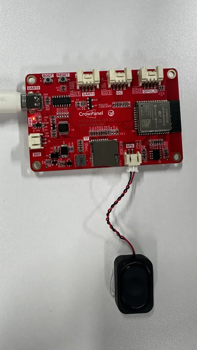
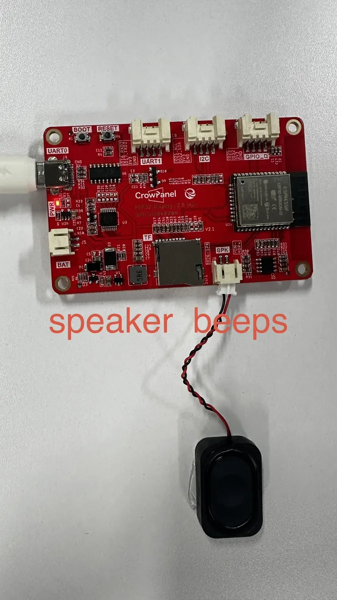
The image below captures the speaker test status after the example runs. The cyclical rhythm of "sound for 1 second, pause for 2 seconds".
Example4: Initialize SD Card slot
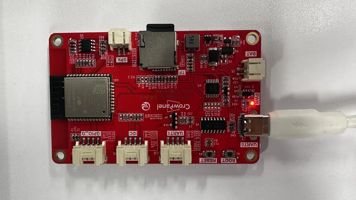
Please insert an SD card formatted as FAT16 or FAT32. Other file system formats may fail to be read.
#include <Wire.h>
#include <SPI.h>
#include <SD.h>
#include <FS.h>

/*---------------------------------------------------------------
 * SD card SPI configuration
 * These pins connect the ESP32 SPI controller to the onboard card slot.
 *--------------------------------------------------------------*/
#define SD_MOSI 23
#define SD_MISO 19
#define SD_SCK 18
#define SD_CS 5

/**
 * @brief Start the serial monitor, SPI bus, and SD card demonstration.
 *
 * Arduino calls this function once after power-up or reset. A return value of
 * one from SD_init() means the card could not be mounted or identified.
 *
 * @param None.
 * @return Nothing.
 */
void setup() {
  Serial.begin(9600);
  SPI.begin(SD_SCK, SD_MISO, SD_MOSI);
  delay(100);

  if (SD_init() == 1) {
    Serial.println("Card Mount Failed");
  } else {
    Serial.println("initialize SD Card successfully");
  }
}

/**
 * @brief Leave the card contents unchanged after the startup test.
 *
 * Arduino calls this function repeatedly after setup(). All card inspection is
 * intentionally performed once during startup.
 *
 * @param None.
 * @return Nothing.
 */
void loop() {
}

/**
 * @brief Mount the SD card, report its capacity, and list stored files.
 *
 * setup() calls this function once after the SPI bus has stabilized. Only read
 * operations are active; the commented examples show optional file operations.
 *
 * @param None.
 * @return 0 when the card is ready, or 1 when mounting or detection fails.
 */
int SD_init() {
  if (!SD.begin(SD_CS)) {
    Serial.println("Card Mount Failed");
    return 1;
  }

  uint8_t cardType = SD.cardType();
  if (cardType == CARD_NONE) {
    Serial.println("No TF card attached");
    return 1;
  }

  uint64_t cardSize = SD.cardSize() / (1024 * 1024);
  Serial.printf("TF Card Size: %lluMB\n", cardSize);
  listDir(SD, "/", 2);

  //  listDir(SD, "/", 0);
  //  createDir(SD, "/mydir");
  //  listDir(SD, "/", 0);
  //  removeDir(SD, "/mydir");
  //  listDir(SD, "/", 2);
  //  writeFile(SD, "/hello.txt", "Hello ");
  //  appendFile(SD, "/hello.txt", "World!\n");
  //  readFile(SD, "/hello.txt");
  //  Serial.printf("Total space: %lluMB\n", SD.totalBytes() / (1024 * 1024));
  //  Serial.printf("Used space: %lluMB\n", SD.usedBytes() / (1024 * 1024));
  //  Serial.println("SD init over.");

  return 0;
}

/**
 * @brief Recursively list files below a directory.
 *
 * SD_init() calls this function after a successful mount. Directory recursion
 * stops when levels reaches zero, which prevents an unrestricted tree walk.
 *
 * @param fs Mounted filesystem that owns the directory.
 * @param dirname Absolute directory path to inspect.
 * @param levels Maximum number of nested directory levels to visit.
 * @return Nothing.
 */
void listDir(fs::FS &fs, const char *dirname, uint8_t levels) {
  //  Serial.printf("Listing directory: %s\n", dirname);

  File root = fs.open(dirname);
  if (!root) {
    // Serial.println("Failed to open directory");
    return;
  }
  if (!root.isDirectory()) {
    Serial.println("Not a directory");
    return;
  }

  File file = root.openNextFile();
//  i = 0;
  while (file) {
    if (file.isDirectory()) {
      // Serial.print("  DIR : ");
      // Serial.println(file.name());
      if (levels) {
        listDir(fs, file.name(), levels - 1);
      }
    } else {
      Serial.print("FILE: ");
      Serial.print(file.name());
//    lcd.setCursor(0, 2 * i);
//    lcd.printf("FILE:%s", file.name());

      Serial.print("SIZE: ");
      Serial.println(file.size());
//    lcd.setCursor(180, 2 * i);
//    lcd.printf("SIZE:%d", file.size());
//    i += 16;
    }

    file = root.openNextFile();
  }
}
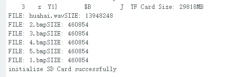
The figure below shows the card capacity, file names, and file sizes output in the serial monitor.
Example5: Initialize the touch
Make sure the TFT_eSPI library is installed. Upload the following code to the ESP display, and open the serial monitor to check the touch information.
#include <TFT_eSPI.h>

/*---------------------------------------------------------------
 * Touchscreen state and calibration
 * The stored calibration maps raw controller readings to screen pixels.
 *--------------------------------------------------------------*/
TFT_eSPI lcd = TFT_eSPI();
uint16_t touchX, touchY;
uint16_t calData[5] = {557, 3263, 369, 3493, 3};

/**
 * @brief Initialize the LCD and load the saved touch calibration.
 *
 * Arduino calls this function once after power-up or reset. The interactive
 * calibration call remains disabled because valid values are already stored.
 *
 * @param None.
 * @return Nothing.
 */
void setup() {
  Serial.begin(9600);
  lcd.begin();
  lcd.setRotation(1);

  /*-------------------------------------------------------------
   * Select one calibration method
   * Enable touch_calibrate() only when new panel values are needed.
   *------------------------------------------------------------*/
//  touch_calibrate();
  lcd.setTouch(calData);
}

/**
 * @brief Read touches and print their calibrated pixel coordinates.
 *
 * Arduino calls this function repeatedly after setup(). A pressure threshold
 * of 600 filters light contact and electrical noise.
 *
 * @param None.
 * @return Nothing.
 */
void loop() {
  bool touched = lcd.getTouch(&touchX, &touchY, 600);
  if (touched) {
    Serial.print("Data x ");
    Serial.println(touchX);

    Serial.print("Data y ");
    Serial.println(touchY);
  }
}

/**
 * @brief Run the TFT_eSPI corner calibration and print reusable values.
 *
 * setup() may call this function instead of lcd.setTouch() when the panel is
 * first commissioned or its orientation changes. Follow the on-screen targets,
 * then copy the printed array into the global calData definition.
 *
 * @param None.
 * @return Nothing.
 */
void touch_calibrate() {
  uint16_t calData[5];
  uint8_t calDataOK = 0;
  Serial.println("Touch-screen calibration");
  Serial.println("Please touch the corners as directed");

//  lv_timer_handler();
  lcd.calibrateTouch(calData, TFT_MAGENTA, TFT_BLACK, 15);
  Serial.println("calibrateTouch(calData, TFT_MAGENTA, TFT_BLACK, 15)");
  Serial.println();
  Serial.println();
  Serial.println("//Use this calibration code in setup():");
  Serial.print("uint16_t calData[5] = ");
  Serial.print("{ ");

  for (uint8_t i = 0; i < 5; i++) {
    Serial.print(calData[i]);
    if (i < 4) Serial.print(", ");
  }

  Serial.println(" };");
  Serial.print("  tft.setTouch(calData);");
  Serial.println();
  Serial.println();
}
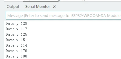
The figure below shows the X and Y coordinates continuously output by the serial monitor when the touchscreen is pressed.
Example6: BLE
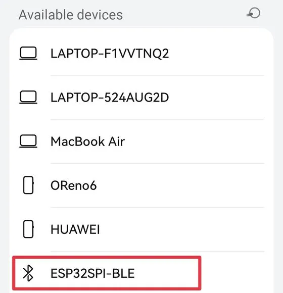
Upload the following code to the board, and use the phone to search the Bluetooth device.
#include "BLEDevice.h"
#include "BLEServer.h"
#include "BLEUtils.h"
#include "BLE2902.h"
#include <BLECharacteristic.h>

/*---------------------------------------------------------------
 * BLE identity and attribute UUIDs
 * A client discovers the advertised service and accesses its characteristic.
 *--------------------------------------------------------------*/
#define bleServerName "ESP32SPI-BLE"
#define SERVICE_UUID "6479571c-2e6d-4b34-abe9-c35116712345"
#define CHARACTERISTIC_UUID "826f072d-f87c-4ae6-a416-6ffdcaa02d73"

// Points to the advertising controller used to make the service discoverable.
BLEAdvertising* pAdvertising = NULL;
// Owns BLE connections and dispatches connection callbacks.
BLEServer* pServer = NULL;
// Groups the characteristic under the UUID advertised by this example.
BLEService *pService = NULL;
// Stores the readable, writable, and notifiable ELECROW value.
BLECharacteristic* pCharacteristic = NULL;
// Records whether a client currently has an active server connection.
bool connected_state = false;

/*---------------------------------------------------------------
 * BLE connection state callbacks
 * The BLE stack invokes this class when a client connects or disconnects.
 *--------------------------------------------------------------*/
class MyServerCallbacks: public BLEServerCallbacks {
  /**
   * @brief Record that a BLE client has connected.
   *
   * The BLE stack calls this function when it accepts a connection.
   *
   * @param pServer Server that accepted the connection.
   * @return Nothing.
   */
  void onConnect(BLEServer *pServer) {
    connected_state = true;
  }

  /**
   * @brief Record that the BLE client has disconnected.
   *
   * The BLE stack calls this function when the active connection closes.
   *
   * @param pServer Server whose connection closed.
   * @return Nothing.
   */
  void onDisconnect(BLEServer *pServer) {
    connected_state = false;
  }
};

/**
 * @brief Create and advertise the BLE service and characteristic.
 *
 * Arduino calls this function once after power-up or reset. A client can read
 * the initial ELECROW value, write a new value, or subscribe to notifications.
 *
 * @param None.
 * @return Nothing.
 */
void setup() {
  Serial.begin(115200);

  BLEDevice::init(bleServerName);
  pServer = BLEDevice::createServer();
  pServer->setCallbacks(new MyServerCallbacks());
  pService = pServer->createService(SERVICE_UUID);

  pCharacteristic = pService->createCharacteristic(
                      CHARACTERISTIC_UUID,
                      BLECharacteristic::PROPERTY_READ | BLECharacteristic::PROPERTY_WRITE | BLECharacteristic::PROPERTY_NOTIFY);
  pCharacteristic->setValue("ELECROW");

  pAdvertising = BLEDevice::getAdvertising();
  pAdvertising->addServiceUUID(SERVICE_UUID);
  pAdvertising->start();
  pService->start();
  //  pAdvertising->stop();
  //  pService->stop();
}

/**
 * @brief Keep the BLE stack active after one-time server configuration.
 *
 * Arduino calls this function repeatedly after setup(). BLE events are handled
 * asynchronously by the stack and the registered callbacks.
 *
 * @param None.
 * @return Nothing.
 */
void loop() {
}
The figure below shows the service and characteristic value page after a phone BLE debugging tool discovers and connects to ESP32SPI-BLE.
Example7: Initialize Wi-Fi
Upload the following code to the ESP display. Note: change the Wi-Fi SSID and password to your own.
#include <WiFi.h>

/*---------------------------------------------------------------
 * Wireless network credentials
 * Replace these demonstration values with the local 2.4 GHz network.
 *--------------------------------------------------------------*/
const char *ssid = "elecrow888";
const char *password = "elecrow2014";

/**
 * @brief Connect the ESP32 to Wi-Fi and report its assigned IP address.
 *
 * Arduino calls this function once after power-up or reset. Execution remains
 * in the connection loop until the access point accepts the device.
 *
 * @param None.
 * @return Nothing.
 */
void setup() {
  Serial.begin(115200);
  WiFi.begin(ssid, password);
  WiFi.setAutoReconnect(true);

  while (WiFi.status() != WL_CONNECTED) {
    delay(100);
    Serial.println("connecting");
  }

  Serial.println("WiFi is connected.");
  Serial.println("IP address: ");
  Serial.println(WiFi.localIP());
//  WiFi.disconnect();
}

/**
 * @brief Keep the sketch active after the one-time connection procedure.
 *
 * Arduino calls this function repeatedly after setup(). Automatic reconnection
 * is handled by the Wi-Fi stack, so no foreground work is required here.
 *
 * @param None.
 * @return Nothing.
 */
void loop() {
}
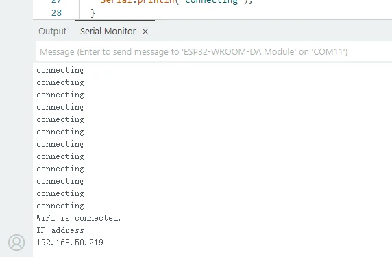
The screenshot below shows the serial monitor displaying the successful connection and the device's local IP address.
Example8: Connect Crowtail-GPS module via UART to Get Location
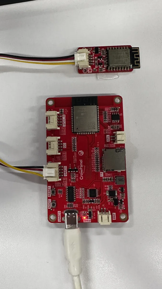
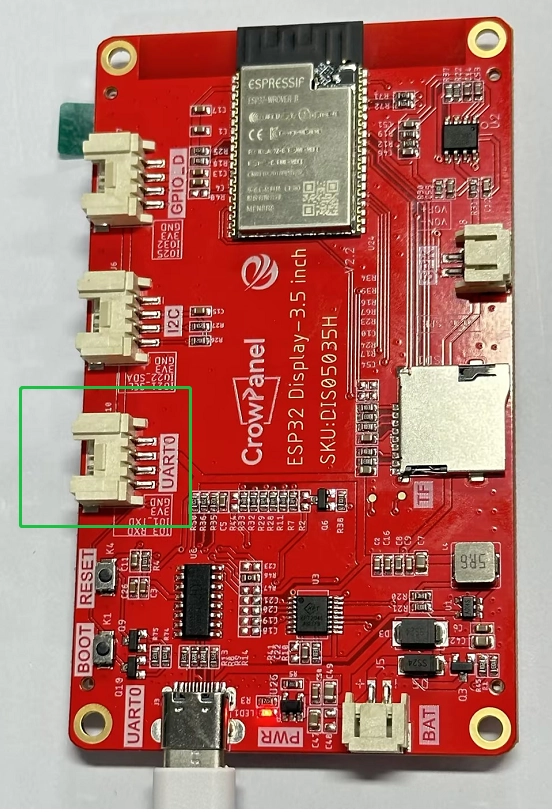
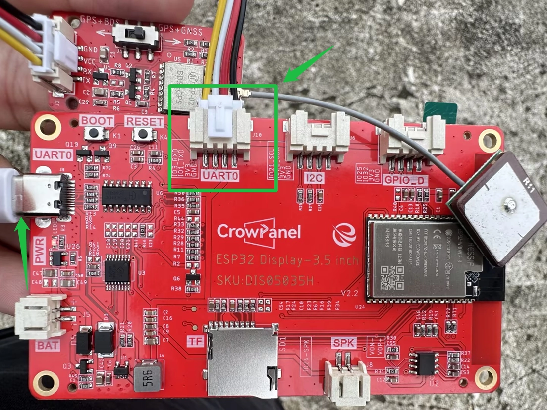
Because the USB-to-serial interface shares the same pins as the UART interface, the USB and UART functions cannot be used at the same time. Leave the UART interface disconnected when flashing/uploading the firmware.
#include <TFT_eSPI.h>
#include <Arduino.h>

/*---------------------------------------------------------------
 * GPS serial connection
 * UART2 receives NMEA data through GPIO3 and transmits through GPIO1.
 *--------------------------------------------------------------*/
#define GPS_RX 3
#define GPS_TX 1
HardwareSerial gpsSerial(2);

// Provides drawing access to the onboard 480 x 320 LCD.
TFT_eSPI lcd = TFT_eSPI();

/*---------------------------------------------------------------
 * Display geometry
 * These dimensions define the coordinate space used by drawScreen().
 *--------------------------------------------------------------*/
#define SCREEN_W 480
#define SCREEN_H 320

// Accumulates one NMEA sentence without dynamic memory allocation.
char nmeaLine[128];
// Points to the next free byte in nmeaLine.
byte nmeaIndex = 0;

/*---------------------------------------------------------------
 * Parsed navigation state
 * GGA, RMC, and VTG sentences update the fields shown on the LCD.
 *--------------------------------------------------------------*/
struct {
  bool valid = false;
  float lat = 0;
  float lon = 0;
  char latDir = 'N';
  char lonDir = 'E';
  float alt = 0;
  float speed = 0;
  uint8_t sats = 0;
  uint8_t fixType = 0; // 0 = no fix, 1 = GPS fix, 2 = differential GPS fix.
  char timeStr[10] = "--:--:--";
  char dateStr[12] = "----/--/--";
} gps;

/**
 * @brief Validate one complete NMEA sentence with its XOR checksum.
 *
 * handleNMEA() calls this function before parsing a received line. Rejecting
 * damaged sentences prevents partial serial data from reaching the display.
 *
 * @param line Null-terminated NMEA sentence beginning with '$'.
 * @return true when the calculated checksum matches the received checksum.
 * @return false when the sentence is incomplete or corrupted.
 */
bool checkNMEA(const char* line) {
  const char* star = strchr(line, '*');
  if (!star || strlen(star) < 3) return false;

  byte calc = 0;
  for (const char* p = line + 1; *p && *p != '*'; p++) {
    calc ^= *p;
  }

  byte recv = (byte)strtol(star + 1, NULL, 16);
  return calc == recv;
}

/**
 * @brief Convert an NMEA degrees-minutes coordinate to decimal degrees.
 *
 * GGA and RMC parsers call this function after extracting a coordinate. South
 * and west positions become negative so the result follows common map notation.
 *
 * @param dm Coordinate in ddmm.mmmm or dddmm.mmmm format.
 * @param dir Hemisphere letter: N, S, E, or W.
 * @return Signed coordinate in decimal degrees, or 0 for invalid input.
 */
float dmToDd(const char* dm, char dir) {
  if (!dm || strlen(dm) < 3) return 0;
  float val = atof(dm);
  int deg = (int)(val / 100);
  float min = val - deg * 100;
  float dd = deg + min / 60.0;
  return (dir == 'S' || dir == 'W') ? -dd : dd;
}

/**
 * @brief Parse fix quality, satellites, altitude, time, and coordinates from GGA.
 *
 * handleNMEA() calls this function for a checksum-verified GPGGA or GNGGA
 * sentence. strtok() edits the sentence buffer while walking its fields.
 *
 * @param p Writable, null-terminated GGA sentence.
 * @return Nothing.
 */
void parseGGA(char* p) {
  // $GPGGA,hhmmss.ss,lat,N,lon,E,fix,sats,hdop,alt,M,...
  char* tok = strtok(p, ","); // $GPGGA
  tok = strtok(NULL, ","); // time
  if (tok && strlen(tok) >= 6) {
    snprintf(gps.timeStr, sizeof(gps.timeStr), "%c%c:%c%c:%c%c",
             tok[0], tok[1], tok[2], tok[3], tok[4], tok[5]);
  }
  tok = strtok(NULL, ","); // lat
  char* lat = tok;
  tok = strtok(NULL, ","); // N/S
  char latD = tok ? tok[0] : 'N';
  tok = strtok(NULL, ","); // lon
  char* lon = tok;
  tok = strtok(NULL, ","); // E/W
  char lonD = tok ? tok[0] : 'E';
  tok = strtok(NULL, ","); // fix
  gps.fixType = tok ? atoi(tok) : 0;
  gps.valid = (gps.fixType > 0);
  tok = strtok(NULL, ","); // sats
  gps.sats = tok ? atoi(tok) : 0;
  tok = strtok(NULL, ","); // hdop
  tok = strtok(NULL, ","); // alt
  gps.alt = (tok && strlen(tok) > 0) ? atof(tok) : 0;

  if (gps.valid) {
    gps.lat = dmToDd(lat, latD);
    gps.lon = dmToDd(lon, lonD);
    gps.latDir = latD;
    gps.lonDir = lonD;
  }
}

/**
 * @brief Parse validity, position, speed, and date from an RMC sentence.
 *
 * handleNMEA() calls this function for a checksum-verified GPRMC or GNRMC
 * sentence. Speed is converted from knots to kilometres per hour.
 *
 * @param p Writable, null-terminated RMC sentence.
 * @return Nothing.
 */
void parseRMC(char* p) {
  // $GPRMC,time,status,lat,N,lon,E,speed,course,date,...
  char* tok = strtok(p, ","); // $GPRMC
  tok = strtok(NULL, ","); // time
  tok = strtok(NULL, ","); // status A/V
  gps.valid = (tok && tok[0] == 'A');
  tok = strtok(NULL, ","); // lat
  char* lat = tok;
  tok = strtok(NULL, ","); // N/S
  char latD = tok ? tok[0] : 'N';
  tok = strtok(NULL, ","); // lon
  char* lon = tok;
  tok = strtok(NULL, ","); // E/W
  char lonD = tok ? tok[0] : 'E';
  tok = strtok(NULL, ","); // speed knots
  gps.speed = (tok && strlen(tok) > 0) ? atof(tok) * 1.852 : 0;
  tok = strtok(NULL, ","); // course
  tok = strtok(NULL, ","); // date
  if (tok && strlen(tok) == 6) {
    snprintf(gps.dateStr, sizeof(gps.dateStr), "20%c%c/%c%c/%c%c",
             tok[4], tok[5], tok[2], tok[3], tok[0], tok[1]);
  }

  if (gps.valid) {
    gps.lat = dmToDd(lat, latD);
    gps.lon = dmToDd(lon, lonD);
    gps.latDir = latD;
    gps.lonDir = lonD;
  }
}

/**
 * @brief Read the kilometres-per-hour field from a VTG sentence.
 *
 * handleNMEA() calls this function when VTG data is available. The result acts
 * as an additional speed source alongside RMC.
 *
 * @param p Writable, null-terminated VTG sentence.
 * @return Nothing.
 */
void parseVTG(char* p) {
  char* tok = strtok(p, ","); // $GPVTG
  tok = strtok(NULL, ","); // true track
  tok = strtok(NULL, ","); // T
  tok = strtok(NULL, ","); // mag track
  tok = strtok(NULL, ","); // M
  tok = strtok(NULL, ","); // speed knots
  tok = strtok(NULL, ","); // N
  tok = strtok(NULL, ","); // speed km/h
  if (tok && strlen(tok) > 0) {
    gps.speed = atof(tok);
  }
}

/**
 * @brief Validate and dispatch the NMEA sentence stored in nmeaLine.
 *
 * loop() calls this function after receiving a line terminator. Short or
 * checksum-invalid lines are discarded, and sentence types not shown on the
 * display are intentionally ignored.
 *
 * @param None.
 * @return Nothing.
 */
void handleNMEA() {
  if (nmeaIndex < 10) return;
  nmeaLine[nmeaIndex] = '\0';

  if (!checkNMEA(nmeaLine)) return;

  /*-------------------------------------------------------------
   * Dispatch supported navigation sentences
   * Accept both the legacy GP talker ID and multi-constellation GN ID.
   *------------------------------------------------------------*/
  if (strncmp(nmeaLine, "$GPGGA", 6) == 0 || strncmp(nmeaLine, "$GNGGA", 6) == 0) {
    parseGGA(nmeaLine);
  }
  else if (strncmp(nmeaLine, "$GPRMC", 6) == 0 || strncmp(nmeaLine, "$GNRMC", 6) == 0) {
    parseRMC(nmeaLine);
  }
  else if (strncmp(nmeaLine, "$GPVTG", 6) == 0 || strncmp(nmeaLine, "$GNVTG", 6) == 0) {
    parseVTG(nmeaLine);
  }
  // GSA, GSV, GLL, and other sentences do not feed this screen.
}

/**
 * @brief Redraw the LCD with either acquisition status or navigation data.
 *
 * loop() calls this function every 800 ms. A valid fix shows coordinates,
 * altitude, speed, satellite count, and date; otherwise the screen explains
 * that the receiver is still acquiring satellites.
 *
 * @param None.
 * @return Nothing.
 */
void drawScreen() {
  // Retained for the original screen-state tracking design.
  static bool lastValid = false;

  // A full redraw keeps stale values off screen and is fast enough here.
  lcd.fillScreen(TFT_WHITE);

  // Title bar
  lcd.fillRect(0, 0, SCREEN_W, 36, gps.valid ? 0x1B5E : 0xC000);
  lcd.setTextColor(TFT_WHITE);
  lcd.setTextSize(2);
  lcd.drawString(gps.valid ? "  GPS LOCKED" : "  NO SIGNAL", 8, 8);

  // Keep the latest receiver time visible in both fix states.
  lcd.setTextSize(1);
  lcd.drawString(gps.timeStr, 240, 14);

  // Main content
  lcd.setTextColor(TFT_BLACK, TFT_WHITE);
  lcd.setTextSize(2);
  int y = 48;
  const int lh = 26; // line height
  char buf[48];

  if (!gps.valid) {
    // Hide invalid navigation values until the receiver reports a valid fix.
    lcd.setTextSize(3);
    lcd.setTextColor(0xC000);
    lcd.drawString("Acquiring...", 50, 100);
    lcd.setTextSize(2);
    lcd.setTextColor(TFT_DARKGREY);
    snprintf(buf, sizeof(buf), "Satellites: %d", gps.sats);
    lcd.drawString(buf, 80, 150);
    lcd.drawString("Please wait...", 80, 180);
    return;
  }

  /*-------------------------------------------------------------
   * Draw valid navigation data
   * Coordinates use the largest font; supporting values remain compact.

   *------------------------------------------------------------*/
  lcd.setTextSize(3);
  snprintf(buf, sizeof(buf), "%.5f", gps.lat);
  lcd.drawString(buf, 10, y);
  y += 36;

  snprintf(buf, sizeof(buf), "%.5f", gps.lon);
  lcd.drawString(buf, 10, y);
  y += 44;

  // Divider line
  lcd.fillRect(10, y - 4, 300, 2, TFT_LIGHTGREY);

  // Detailed info (small font)
  lcd.setTextSize(2);

  // Altitude
  snprintf(buf, sizeof(buf), "ALT  %.1f m", gps.alt);
  lcd.drawString(buf, 10, y);

  // Speed
  snprintf(buf, sizeof(buf), "SPD  %.1f", gps.speed);
  lcd.drawString(buf, 170, y);
  lcd.setTextSize(1);
  lcd.drawString("km/h", 280, y + 8);
  lcd.setTextSize(2);
  y += lh;

  // Satellite count + Date
  snprintf(buf, sizeof(buf), "SAT  %d", gps.sats);
  lcd.drawString(buf, 10, y);

  lcd.setTextSize(1);
  lcd.setTextColor(TFT_DARKGREY);
  lcd.drawString(gps.dateStr, 200, y + 8);
}

/**
 * @brief Initialize the debug port, GPS UART, LCD, and startup screen.
 *
 * Arduino calls this function once after power-up or reset. The startup screen
 * remains visible until loop() performs the first scheduled redraw.
 *
 * @param None.
 * @return Nothing.
 */
void setup() {
  Serial.begin(115200);
  gpsSerial.begin(9600, SERIAL_8N1, GPS_RX, GPS_TX);

  lcd.begin();
  lcd.setRotation(1);
  pinMode(27, OUTPUT);
  digitalWrite(27, HIGH);

  /*-------------------------------------------------------------
   * Show immediate startup feedback
   * This confirms the LCD path before a satellite fix is available.
   *------------------------------------------------------------*/
  lcd.fillScreen(TFT_WHITE);
  lcd.setTextColor(TFT_BLACK);
  lcd.setTextSize(2);
  lcd.drawString("GPS Display", 100, 90);
  lcd.setTextSize(1);
  lcd.setTextColor(TFT_DARKGREY);
  lcd.drawString("Waiting for satellites...", 85, 130);

  Serial.println("GPS Display ready");
}

/**
 * @brief Assemble incoming NMEA lines and refresh the navigation display.
 *
 * Arduino calls this function repeatedly after setup(). Serial bytes are stored
 * until a line terminator arrives, then a bounded 800 ms display interval keeps
 * the screen readable while reception continues at full speed.
 *
 * @param None.
 * @return Nothing.
 */
void loop() {
  /*-------------------------------------------------------------
   * Assemble one complete NMEA sentence
   * The size check reserves one byte for the terminating null character.
   *------------------------------------------------------------*/
  while (gpsSerial.available()) {
    char c = gpsSerial.read();
    if (c == '\n' || c == '\r') {
      if (nmeaIndex > 0) {
        handleNMEA();
        nmeaIndex = 0;
      }
    } else if (nmeaIndex < sizeof(nmeaLine) - 1) {
      nmeaLine[nmeaIndex++] = c;
    }
  }

  // Limit full-screen redraws to reduce visible flicker.
  static uint32_t lastDraw = 0;
  if (millis() - lastDraw > 800) {
    drawScreen();
    lastDraw = millis();
  }
}
Once the program has been successfully uploaded, connect the GPS module and reconnect power to the board via the USB port.
GPS module purchase link: https://www.elecrow.com/crowtailgps-p-1515.html.
Note: For best results, choose a location with good weather and an open outdoor environment. This allows the GPS module to receive satellite signals properly, collect data, and display it on the screen.